Page 889 of 1807

W03534
21E 1G
1E1G II1
IF1
IF1
II1
1E 1B3
7
9
4
2
131211 21
2
Battery
1B
5 11 DLC1
Relay Block No.2
ALT
Power
Power
Airbag Sensor
Assembly
Junction Block No.1
Junction Block No.1
SRS Waring Light215
Junction Block No.1
*1: 2JZ-GE Engine
*2: 2JZ-GTE Engine ECU-BTc
ABB (*1)
(*2) B-Y
LA 12
W-RP-B R (*1)
(*2)
P-B
P-B
2
2A2P-B
7
Tc
W-L
ABTc DLC2
R
4
12B-Y
B B
B
B DI-598
- DIAGNOSTICSSUPPLEMENTAL RESTRAINT SYSTEM
826 Author�: Date�:
1997 SUPRA (RM502U)
SRS Warning Light System Malfunction (Always lit up, when igni-
tion switch is in LOCK position.)
CIRCUIT DESCRIPTION
The SRS warning light is located on the combination meter.
When the SRS is normal, the SRS warning light lights up for approx. 6 seconds after the ignition switch is
turned from LOCK position to ACC or ON position, and then turns off automatically.
If there is a malfunction in the SRS, the SRS warning light lights up to inform the driver of the abnormality.
When terminals Tc and E
1 of the DLC1 are connected, the DTC is displayed by the blinking of the SRS warn-
ing light.
WIRING DIAGRAM
DI4WS-01
Page 891 of 1807
 (-)
DI-600
- DIAGNOSTICSSUPPLEMENTAL RESTRAINT SYSTEM
828 Author�: Date�:
1997 SUPRA (RM502U)
SRS Warning Light System Malfunction (Does not light up, when
ignition switch is in turn")
N14677
Fuse
(+) (-)
DI-600
- DIAGNOSTICSSUPPLEMENTAL RESTRAINT SYSTEM
828 Author�: Date�:
1997 SUPRA (RM502U)
SRS Warning Light System Malfunction (Does not light up, when
ignition switch is in turned to ACC or ON.)
CIRCUIT DESCRIPTION
The SRS warning light is located on the combination meter.
When the SRS is normal, the SRS warning light lights up for approx. 6 seconds after the ignition switch is
turned from LOCK position to ACC or ON position, and then turns off automatically.
If there is a malfunction in the SRS, the SRS warning light lights up to inform the driver of the abnormality.
When terminals Tc and E
1 of the DLC1 are connected, the DTC is displayed by the blinking of the SRS warn-
ing light.
WIRING DIAGRAM
Refer to page DI-598 for the WIRING DIAGRAM.
INSPECTION PROCEDURES
1 Check ECU-B Fuse.
PREPARATION:
Remove the ECU-B fuse.
CHECK:
Check the continuity of ECU-B fuse.
OK:
Continuity
HINT:
�Fuse may be burnt out even if it appears to be OK during
visual inspection.
�If fuse is OK, install it.
NG Go to step 5.
OK
2 Preparation (See step 1 on page DI-595).
DI4WT-01
Page 894 of 1807
H03189
Airbag Sensor
Assembly
Tc
7 21
II1 113
Tc
E1DLC1
BR P-B7
1E 1G
Junction Block No.1 P-B
R (*1)
P-B (*2) 3
11
IF1 R
Tc E1
DTC2 BR 18
IJ1 BR
BR
ED
*1: 2JZ-GE
*2: 2JZ-GTE
R-B
4 3P-B
- DIAGNOSTICSSUPPLEMENTAL RESTRAINT SYSTEM
DI-603
831 Author�: Date�:
1997 SUPRA (RM502U)
Tc Terminal Circuit
CIRCUIT DESCRIPTION
By connecting terminals Tc and E1 of the DLC1 the airbag sensor assembly is set in the DTC output mode.
The DTCs are displayed by the blinking of the SRS warning light.
WIRING DIAGRAM
DI4WU-02
Page 895 of 1807
H03186
ACC
ON
or LOCK
AB0118
R14305AB0119
H00030
ACC
ON
or
(-)DLC 1
(+)Tc E
1
DI-604
- DIAGNOSTICSSUPPLEMENTAL RESTRAINT SYSTEM
832 Author�: Date�:
1997 SUPRA (RM502U)
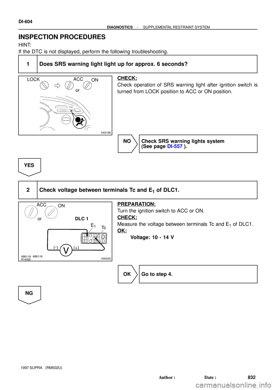
INSPECTION PROCEDURES
HINT:
If the DTC is not displayed, perform the following troubleshooting.
1 Does SRS warning light light up for approx. 6 seconds?
CHECK:
Check operation of SRS warning light after ignition switch is
turned from LOCK position to ACC or ON position.
NO Check SRS warning lights system
(See page DI-557).
YES
2 Check voltage between terminals Tc and E1 of DLC1.
PREPARATION:
Turn the ignition switch to ACC or ON.
CHECK:
Measure the voltage between terminals Tc and E1 of DLC1.
OK:
Voltage: 10 - 14 V
OK Go to step 4.
NG
Page 898 of 1807
AB0117
W02764H00050
LOCK
Airbag Sensor Assembly
(-)Tc
(+)
- DIAGNOSTICSSUPPLEMENTAL RESTRAINT SYSTEM
DI-607
835 Author�: Date�:
1997 SUPRA (RM502U)
If the DTC is displayed without a DTC check procedure, perform the following
troubleshooting.
1 Check resistance between terminal Tc of airbag sensor assembly and body
ground.
PREPARATION:
(a) Turn the ignition switch to LOCK.
(b) Disconnect negative (-) terminal cable from the battery,
and wait at least 90 seconds.
(c) Disconnect the airbag sensor assembly connector.
CHECK:
Check the resistance between terminal Tc of airbag sensor as-
sembly connector and body ground.
OK:
Resistance: 1 MW or higher
NG Repair or replace harness or connector.
OK
Replace airbag sensor assembly.
Page 954 of 1807

BE4032
BE4033I00021
0.25 sec.
0.25 sec. Normal Code
Malfunction codes 11 and 21
4 sec.0.5 sec.
1.5 sec.
1.5 sec. 0.5 sec.
2.5 sec.
ON
OFF
Code 11 Code 21 ON
OFF
N09348
TOYOTA Hand-Held Tester
TOYOTA Break-out-box
N09001DOME Fuse
R/B No.2
I02735
- DIAGNOSTICSCRUISE CONTROL SYSTEM
DI-663
891 Author�: Date�:
1997 SUPRA (RM502U)
HINT:
�If the DTC is not output, inspect the diagnosis circuit (See
page DI-708).
�As an example, the blinking patterns for codes; normal,
11 and 21 are shown in the illustration.
2. ECU TERMINAL VALUES MEASUREMENT BY USING
TOYOTA BRAKE-OUT-BOX AND TOYOTA HAND-
HELD TESTER
(a) Hook up the TOYOTA break- out- box and TOYOTA
hand-held tester to the vehicle.
(b) Read the ECU input/output values by following the
prompts on the tester screen.
(c) Please refer to the TOYOTA hand-held tester has a
ºSnapshotº function. This records the measured data and
is effective in the diagnosis of intermittent problems.
3. DTC CLEARANCE
(a) After completing repairs, the DTC retained in memory can
be cleared by removing the DOME fuse for 10 seconds or
more, with the ignition switch off.
(b) Check that the normal code is displayed after connecting
the fuse.
4. PROBLEM SYMPTOM CONFIRMATION (Road Test)
(a) Inspection the SET switch.
(1) Push the main switch ON.
(2) Drive at a desired speed (40 km/h (25 mph) or high-
er).
(3) Press the control switch to the SET/COAST.
(4) After releasing the switch, check that the vehicle
cruises at the desired speed.
Page 957 of 1807

(2)
(1)
No.
Operation MethodCRUISE MAIN Indicator Light
Blinking PatternDiagnosis
1
3
4
2Turn SET/COAST switch ON
Turn RES/ACC switch ON
Drive at about 40 km/h
(25 mph) or below Turn CANCE")
BE6443
(1)
(2)
(1)
No.
Operation MethodCRUISE MAIN Indicator Light
Blinking PatternDiagnosis
1
3
4
2Turn SET/COAST switch ON
Turn RES/ACC switch ON
Drive at about 40 km/h
(25 mph) or below Turn CANCEL switch ON
Turn stop light switch ON
Depress brake pedal
Turn PNP switch OFF
(Shift to except D position)
Turn clutch switch OFF
(Depress clutch pedal)
Drive at about 40 km/h
(25 mph) or higherSET / COAST switch
circuit is normal
RES / ACC switch circuit
is normal
PNP switch circuit is normal CANCEL switch circuit
is normal
Clutch switch circuit is normal
Vehicle Speed Sensor is
normal
Stop light switch circuit
is normal ON
OFF
0.25 sec.
0.25 sec.
1 sec.Light
ON
OFFLight
ON
OFF Light
ON
OFF Light
ON
OFF Light
ON
OFF Light
Switch OFF
Switch ON
Switch ON
Switch OFF DI-666
- DIAGNOSTICSCRUISE CONTROL SYSTEM
894 Author�: Date�:
1997 SUPRA (RM502U)
5. Using TOYOTA hand-held tester:
INPUT SIGNAL CHECK
HINT:
(1) For check No.1 - No.2
�Turn the ignition switch ON.
(2) For check No.3
�Turn ignition switch ON.
�Shift to D position.
(3) For check No.4
�Jack up the vehicle.
�Start the engine.
�Shift to D position.
(a) Press the control switch to SET/COAST or RES/ACC
position and hold it down or hold it up º1º.
(b) Push the main switch ON º2º.
(c) Check that the CRUISE MAIN indicator light blinks twice
or 3 times repeatedly after 3 seconds.
(d) Turn the SET/COAST or RES/ACC switch OFF.
(e) Operate each switch as listed in the table below.
(f) Read the blinking pattern of the CRUISE MAIN indicator
light.
(g) After performing the check, turn the main switch OFF.
HINT:
When 2 or more signals are input to the ECU, the lowest num-
bered code will be displayed first.
Page 958 of 1807

DIAGNOSTIC TROUBLE CODE CHART
If a malfunction code is displayed during the DTC check, check the circuit li")
DI4XM-01
- DIAGNOSTICSCRUISE CONTROL SYSTEM
DI-667
895 Author�: Date�:
1997 SUPRA (RM502U)
DIAGNOSTIC TROUBLE CODE CHART
If a malfunction code is displayed during the DTC check, check the circuit listed for that code in the table
below and proceed to the appropriate page.
DTC No.
(See Page)Detection ItemTrouble Area
11, 15
(DI-673)�Actuator Motor Circuit
�Cruise control actuator motor
�Harness or connector between actuator motor and ECU
� ECU
12
(DI-675)�Actuator Magnetic Clutch Circuit
�Cruise control magnetic clutch
�Harness or connector between ECU and magnetic clutch,
magnetic clutch and body ground
�ECU
14
(DI-677)�Actuator Motor Circuit
�Cruise control actuator motor
�Harness or connector between actuator motor and ECU
� ECU
21
(DI-679)�Vehicle Speed Sensor Circuit
�Vehicle speed sensor
� ECU
�Combination meter
�Harness or connector between vehicle speed sensor and
ECM, ECM and combination meter, combination meter and
ECU
� ECU
23
(DI-681)�Vehicle Speed Sensor Circuit
�Vehicle speed sensor
� Harness or connector (SPD)
� ECU
32
(DI-682)�Control Switch Circuit (Cruise Control Switch)
�Cruise control switch
�Harness or connector between control switch and ECU
�ECU
41�Cruise Control ECU� ECU
42�Source voltage drop�Power source
51
(DI-685)�Idle switch circuit
�Throttle position sensor
�Harness or connector between cruise control ECU and
throttle position sensor
�ECU
HINT:
�1. When 2 or more codes are indicated, the lowest numbered code will be displayed first.
�2. If the inspection ºProceed to next circuit inspection shown on matrix chartº is given in the flow chart
for each circuit, proceed to the circuit with the next highest number in the table to continue check.
�3. If the trouble still reappears even though there are no abnormalities in any of the other circuit, then
check or replace the cruise control ECU as the last step.
�(*) When the vehicle speed decrease on uphill roads, the speed can be set again and driving contin-
ued. (This is not a malfunction.)

P-B (*2) 3
11
IF1 R
Tc E1
DTC2 BR 18
IJ1 BR
BR
ED
*1: 2JZ-GE
*2: 2JZ-GTE
R-B
4 3P-B
- DIAGNOSTICS")