Page 652 of 1807

AT7809
4.5 - 5.5 V
0Turn the wheel
- DIAGNOSTICSENGINE (2JZ-GTE)
DI-239
467 Author�: Date�:
1997 SUPRA (RM502U)
INSPECTION PROCEDURE
1 Check operation of speed")
A00714
ONCheck Harness A
ECM
A2 SP1(+)
AT7809
4.5 - 5.5 V
0Turn the wheel
- DIAGNOSTICSENGINE (2JZ-GTE)
DI-239
467 Author�: Date�:
1997 SUPRA (RM502U)
INSPECTION PROCEDURE
1 Check operation of speedometer.
CHECK:
Drive the vehicle and check if the operation of the speedometer in the combination meter is normal.
HINT:
The No.1 vehicle speed sensor is operating normally if the speedometer display is normal.
NG Check speedometer circuit (See page BE-43).
OK
2 Check voltage between terminal SP1 of ECM connector and body ground.
PREPARATION:
(a) Shift the shift lever to neutral position.
(b) Jack up one of rear wheels.
(c) Connect Check Harness A (See page DI-164).
(d) Disconnect power steering ECU connector and cruise
control ECU connector.
(e) Turn ignition switch ON.
CHECK:
Measure voltage between terminal SP1 of ECM connector and
body ground when rear wheel is turned slowly.
OK:
Voltage is generated intermittently.
NG Check and repair harness and connector be-
tween combination meter and ECM.
OK
Check and replace ECM (See page IN-28).
Page 733 of 1807

DI4V6-01
F02620
R06980
Short Pin
DLC1
S-17-1 Iei-23-1-A
F00041
DLC2
Tc E 1DLC1
Tc E1
R01346
Normal Code
2 sec.
ON
OFF0.25
sec.
0.25
sec.
Code 11 and 21
0.5
sec.
4 sec.1.5
sec.2.5 sec.0.5
sec.
Code 21
Code 11 ON
OFF DI-442
- DIAGNOSTICSANTI-LOCK BRAKE SYSTEM
670 Author�: Date�:
1997 SUPRA (RM502U)
PRE-CHECK
1. DIAGNOSIS SYSTEM
(a) Check the Indicator,
When the ignition switch is turned ON, check that the ABS
warning light goes on for 3 seconds.
HINT:
If the indicator check result is not normal, proceed to trouble-
shooting for the ABS warning light circuit (See page DI-488).
(b) Check the DTC.
(1) Turn the ignition switch ON.
(2) Disconnect the short pin from DLC1.
(3) Using SST, connect terminals Tc and E1 of DLC2 or
DLC1.
SST 09843-18020
(4) Read the DTC from the ABS warning light on the
combination meter.
HINT:
If no code appears, inspect the diagnostic circuit or ABS warn-
ing light circuit (See page DI-494 or DI-488).
As an example, the blinking patterns for normal code and
codes 11 and 21 are shown on the left.
(5) Codes are explained in the code table on page
DI-447.
(6) After completing the check, disconnect terminals Tc
and E1, and turn off the display.
If 2 or more malfunctions are indicated at the same time, the
lowest numbered DTC will be displayed 1st.
Page 735 of 1807

7276
ON
OFF
0.5 sec.
0.5 sec.1.5 sec.
0.5 sec.0.5 sec.2.5 sec.
4 sec.
Repeat DI-444
- DI")
F00007
E1
Tc
Ts
lei-23-1-A
DLC1
BR3904
0.13 sec.
0.13 sec.
ON
OFF
BR3893
Malfunction Code (Example Code 72, 76)
7276
ON
OFF
0.5 sec.
0.5 sec.1.5 sec.
0.5 sec.0.5 sec.2.5 sec.
4 sec.
Repeat DI-444
- DIAGNOSTICSANTI-LOCK BRAKE SYSTEM
672 Author�: Date�:
1997 SUPRA (RM502U)
2. SPEED SENSOR SIGNAL AND DECELERATION SEN-
SOR
(a) Check the speed sensor signal and deceleration sensor.
(1) Turn the ignition switch OFF
(2) Using SST, connect terminal Ts and E1 of DLC1.
SST 09843-18020
(3) Start the engine.
(4) Check that the ABS warning light blinks.
HINT:
�If the ABS warning light does not blink, inspect the ABS
warning light circuit (See page DI-488).
�If the ABS warning light is always on, inspect and repair,
deceleration sensor.
(5) Drive the vehicle faster than 45 km/h (28 mph) for
several seconds.
(6) Stop the vehicle.
(7) Using SST, connect terminals Tc an E1 of DLC1.
SST 09843-18020
(8) Read the number of blinks of the ABS warning light.
HINT:
�See the list of DTC shown on the next page.
�If every sensor is normal, a normal code is output (A cycle
of 0.25 sec. ON and 0.25 sec. OFF is repeated).
�If 2 or more malfunctions are indicated at the same time,
the lowest numbered code will be displayed 1st.
(9) After doing the check, disconnect terminals Ts and
E1, Tc and E1 of DLC1, and turn ignition switch OFF.
Page 738 of 1807

DIAGNOSTIC TROUBLE CODE CHART
If a malfunction code is displayed during the DTC check, check the circuit l")
DI4V7-01
- DIAGNOSTICSANTI-LOCK BRAKE SYSTEM
DI-447
675 Author�: Date�:
1997 SUPRA (RM502U)
DIAGNOSTIC TROUBLE CODE CHART
If a malfunction code is displayed during the DTC check, check the circuit listed for that code. For details
of each code, turn to the page referred to under the ºSee pageº for the respective ºDTC No.º in the DTC chart.
HINT:
�Using SST 09843-18020, connect the terminals Tc and E1, and remove the short pin.
�If any abnormality is not found when inspect each inspection parts, inspect the ECU.
DTC No.
(See Page)Detection ItemTrouble Area
11
(DI-453)Open circuit in ABS solenoid relay circuit�ABS solenoid relay
�Open or short in ABS solenoid relay circuit
12
(DI-453)Short circuit in ABS solenoid relay circuit�ABS solenoid relay
�B+ short in ABS solenoid relay circuit
13*2
(DI-460)Open circuit in ABS motor relay circuit�ABS motor relay
�Open or short in ABS motor relay circuit
14
(DI-460)Short circuit in ABS motor relay circuit�ABS motor relay
�B+ short in ABS motor relay circuit
21
(DI-466)Open or short circuit in 2-position solenoid circuit for right front
wheel�ABS actuator
�Open or short in SFRH or SFRR circuit
22
(DI-466)Open or short circuit in 2-position solenoid circuit for left front
wheel�ABS actuator
�Open or short in SFLH or SFLR circuit
23
(DI-466)Open or short circuit in 2-position solenoid circuit for right rear
wheel�ABS actuator
�Open or short in SRH (SRRH) or SRR (SRRR) circuit
24*1
(DI-466)
Open or short circuit in 2-position solenoid circuit for left rear
wheel�ABS actuator
�Open or short in SRLH or SRLR circuit
31*2
(DI-469)Right front wheel speed sensor signal malfunction
32*2
(DI-469)Left front wheel speed sensor signal malfunction�Right front, left front, right rear and left rear speed sensor
O htihd iit33*2
(DI-469)Right rear wheel speed sensor signal malfunction
�Open or short in each speed sensor circuit
�Speed sensor rotor
34*2
(DI-469)Left rear wheel speed sensor signal malfunction
41
(DI-475)Low battery positive voltage
�Battery
�IC regulator
�Open or short in power source circuit
43*1
(DI-479)
Malfunction in deceleration sensor
(constant output)�Deceleration sensor
�Wire harness for deceleration sensor system
44*1
(DI-480)Open or short in deceleration sensor circuit�Deceleration sensor
�Open or short in deceleration sensor circuit
45*1
(DI-479)Malfunction in deceleration sensor�Deceleration sensor
�Wire harness for deceleration sensor system
49
(DI-482)Open circuit in stop light switch circuit�Open in stop light circuit
51*2
(DI-484)
Pump motor is locked
Open in pump motor ground�ABS pump motor
Always
ON
(DI-485)Malfunction in ECU
IG power source circuit�Battery
�IC regulator
�Open or short in power source circuit
Page 743 of 1807

PROBLEM SYMPTOMS TABLE
If a normal code is displayed during the DTC check but the problem still occurs, ch")
DI4VA-01
DI-452
- DIAGNOSTICSANTI-LOCK BRAKE SYSTEM
680 Author�: Date�:
1997 SUPRA (RM502U)
PROBLEM SYMPTOMS TABLE
If a normal code is displayed during the DTC check but the problem still occurs, check the circuits for each
problem symptom in the order given in the table below and proceed to the relevant troubleshooting page.
NOTICE:
When removing the ECU, turn the IG switch OFF.
SymptomsInspection CircuitSee page
ABS does not operate.
Only when 1. - 4. are all normal and the problem is still occurring, replace the ABS
ECU.
1. Check the DTC, reconfirming that the normal code is output.
2. IG power source circuit.
3. Speed sensor circuit.
4. Check the ABS actuator with a checker.
If abnormal, check the hydraulic circuit for leakage (See page DI-498).
DI-442
DI-475
DI-469
BR-66 or XXX
ABS does not operate
efficiently.
Only when 1. - 4. are all normal and the problem is still occurring, replace the ABS
ECU.
1. Check the DTC, reconfirming that the normal code is output.
2. Speed sensor circuit.
3. Stop light switch circuit.
4. Check the ABS actuator with a checker.
If abnormal, check the hydraulic circuit for leakage (See page DI-498).
DI-442
DI-469
DI-482
BR-66 or BR-66
ABS warning light
abnormal.1. ABS warning light circuit.
2. ABS ECU.DI-488
DTC check cannot be done.
Only when 1. and 2. are all normal and the problem is still occurring, replace the
ABS ECU.
1. ABS warning light circuit.
2. Tc terminal circuit.
DI-488
DI-494
Speed sensor signal check
cannot be done.1. Ts terminal circuit.
2. ABS ECU.DI-496XXX
Page 777 of 1807
DI-486
- DIAGNOSTICSANTI-LOCK BRAKE SYSTEM
714 Author�: Date�:
1997 SUPRA (RM502U)
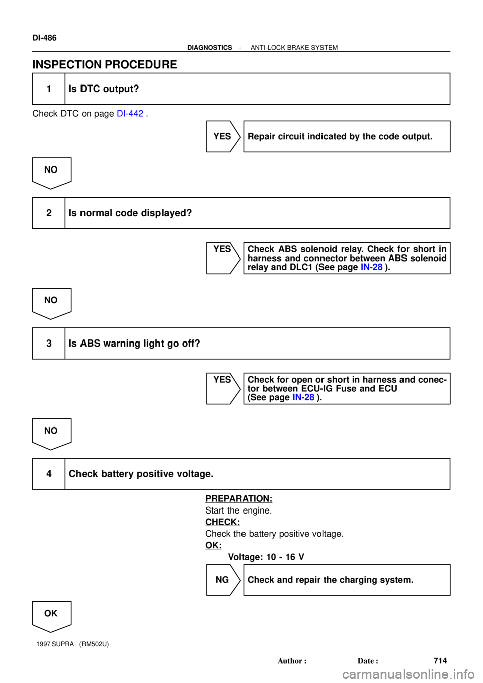
INSPECTION PROCEDURE
1 Is DTC output?
Check DTC on page DI-442.
YES Repair circuit indicated by the code output.
NO
2 Is normal code displayed?
YES Check ABS solenoid relay. Check for short in
harness and connector between ABS solenoid
relay and DLC1 (See page IN-28).
NO
3 Is ABS warning light go off?
YES Check for open or short in harness and conec-
tor between ECU-IG Fuse and ECU
(See page IN-28).
NO
4 Check battery positive voltage.
PREPARATION:
Start the engine.
CHECK:
Check the battery positive voltage.
OK:
Voltage: 10 - 16 V
NG Check and repair the charging system.
OK
Page 785 of 1807
F03361
ABS ECU
12 V
Tc
A20 A1998
*1 *2
R
R
R
IF1
11
P-B
II1 DLC1
R
*121*2P-B R
*1
*2
DLC2
11 Tc E
13
BR
BR BR
ED
IJ1 18BR
Tc E
134
NORMAL ABS (2JZ-GE Engine)
SPORT ABS (2JZ-GTE Engine)
*1:
*2:
S-17-1 Iei-23-1-A
F00041
DLC2
DLC1
E1Tc
E1
Tc
DI-494
- DIAGNOSTICSANTI-LOCK BRAKE SYSTEM
722 Author�: Date�:
1997 SUPRA (RM502U)
Tc Terminal Circuit
CIRCUIT DESCRIPTION
Connecting terminals Tc and E1 of the DLC1 or the DLC1 or the DLC2 causes the ECU to display the DTC
by flashing the ABS warning light.
WIRING DIAGRAM
INSPECTION PROCEDURE
1 Check voltage between terminals Tc and E1 of DLC2 or DLC1.
PREPARATION:
Turn ignition switch ON.
CHECK:
Measure voltage between terminals Tc and E1 of DLC2 or
DLC1.
OK:
Voltage: 10 - 14 V
OK If ABS warning light does not blink even after Tc
and E1 are connected, the ECU may be defec-
tive.
NG
DI4VM-01
Page 793 of 1807
R01346
Normal Code
2 sec.
0.25
sec.
0.25
sec.
ON
OFF
Code 11 and 21
ON
OFF0.5 sec.
2.5 sec. 4.5 sec.1.5
sec. 0.5 sec.
Code 11Code 21
F03366
ECU-B
J/B No.1 DI-502
- DIAGNOSTICSABS & TRACTION CONTROL SYSTEM
730 Author�: Date�:
1997 SUPRA (RM502U)
(3) Read the DTC from the TRAC OFF indicator light on
the combination meter.
HINT:
�If no code appears, inspect the diagnostic circuit or TRAC
OFF indicator light circuit (See page DI-553 or
DI-547).
�As an example, the blinking patterns for normal code and
codes 11 and 21 are shown on the left.
(4) Codes are explained in the code table on page
DI-503.
(5) After completing the check, disconnect terminals Tc
and E1, and turn off the display.
If 2 or more malfunctions are indicated at the same time, the
lowest numbered DTC will be displayed 1st.
(c) Clear the DTC.
(1) Remove the ECU-B fuse from the J/B No.1 for 10
sec. or more.
(2) Install the ECU-B fuse.
(3) Confirm that the TRAC OFF indicator light shows
the normal code.

SPORT ABS (2JZ-GTE Engine)
*1:
*2:
S-17-1")
