Page 1266 of 1807

5
678
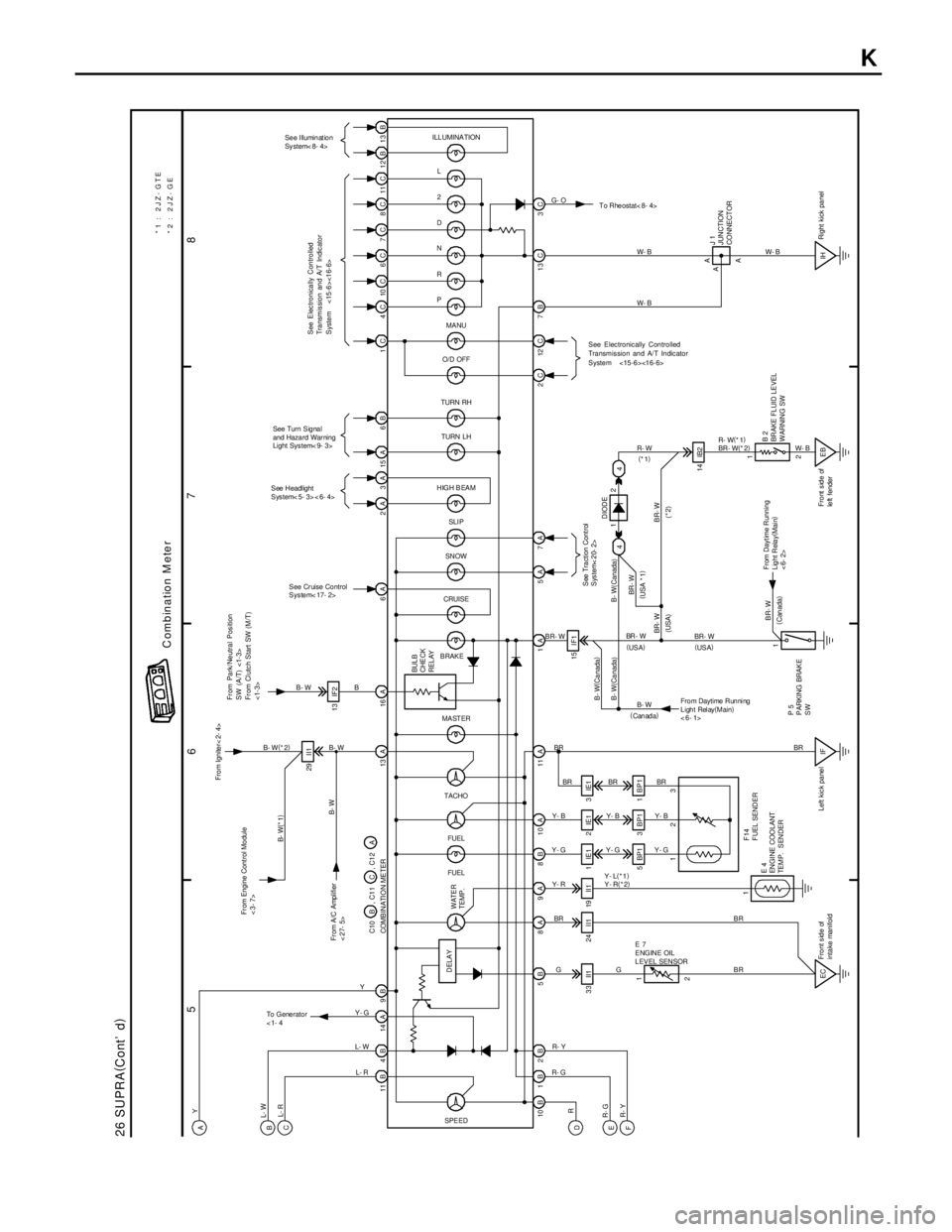
26 SUPRA(
Cont' d)
11B 4B 14A 9B 13A 16A 6A 2A 3A 15A 6B 1C 4C 10C 6C 7C 8C 11C 12B 13B
3C 13 C 7B 12 C 2C 5A 1A 10B1B2B 5B 8A 9A 8B 10A 11A13 IF2
33 II1 24 II1 19 II1
5 BP1 3 B P1 1 B P 1
2 1
IF1
EB IH 14 IB2 1IE1 2IE1 3 IE115 I F1 29 I I1
EC
See Illumination
Sy stem< 8- 4>
See Turn Signal
and Haza rd War ning
Light Sys tem< 9- 3>
See Headlight
Sys tem< 5- 3> < 6- 4>
See Cr uise Co ntrol
Sys te m< 17- 2>To Rheostat< 8- 4> L
2
D
N
R
P
MA NU
O/D OFF
TURN RH
TURN LH
HIGH B EAM
SN OW
CRUISE
BRAKE
SPE EDFUEL FUEL TACHO MA ST ER
Fr om Engine Cont rol Mo dule
<3- 7>Fro m Ignite r< 2- 4>
DELAYBUL B
CHE CK
REL AY
E 7
ENGINE OIL
L EV EL SEN SOR
E 4
EN GI NE COO LANT
TEMP. SENDERF14
F UEL SEND ER
From Daytime Running
Light Relay(
Main)
<6- 1>P 5
P ARKING BRAK E
SWJ 1
JUNCTION
CO NNECT OR
B 2
BR AKE FL UID LE VEL
WARNIN G SW
BR- WW- B
BR - W
B B- W
B- W(
*2)
B- WW- B W- B
W- B R- W(
*1)
BR - W(
*2)
R- W
BR- W
B- W
BRBR
G BR Y- R Y- GY- BBR BR
Y- B
Y- G Y- GY- BBR
Y- L(
*1)
Y- R(
*2)
GBRBR
R- GR- Y
L- R L- W Y- GY
B- W Y
L- W
L- R
R
R- G
R- YB- W(
Ca nada)
B- W(Ca nada)
BR- WBR - W B- W( Canada)
BR- W
BR- WDIODE
(* 2) (
USA * 1)
(USA)
(
Can ada)
(
Canada)(
US A) (
US A) (
*1)
112
ILLUMINATION
*1 : 2JZ- GTE
*2 : 2JZ- GE
WATER
TEMP .
A A 123 COMB IN ATI O N ME TER C10 B , C1 1 C , C1 2 A
Front side of
intake manifoldLeft kic k pa ne lRight kick pa nel Front side of
le ft fender
G- O
A
1
2 4 4
Combination M eter
A
B
C
D
E
F
To G e ne r a t o r
<1- 4
B- W(
*1)
From A/C Amplifier
<27- 5>
From Dayt ime Running
Lig ht Rela y(
Mai n)
<6- 2>
SLI P
7A
See Tra ction Cont rol
System< 20- 2>
See Electronically Controlled
Transmission and A/T Indicator
System <15-6><16-6>
From Park/Neutral Position
SW (A/T) <1-3>
From Clutch Start SW (M/T)
<1-3>
See Electronically Controlled
Transmission and A/T Indicator
System <15-6><16-6>
K
Page 1275 of 1807

S02980
FilterCap
S02981
Vacuum Gauge
EC047-02
- EMISSION CONTROL (2JZ-GTE)EXHAUST GAS RECIRCULATION (EGR) SYSTEM
EC-7
1244 Author�: Date�:
1997 SUPRA (RM502U)
EXHAUST GAS RECIRCULATION
(EGR) SYSTEM
INSPECTION
1. CHECK AND CLEAN FILTER IN EGR VACUUM
MODULATOR
(a) Remove the cap and 2 filters.
(b) Check the filter for contamination or damage.
(c) Using compressed air, clean the filter.
(d) Reinstall the 2 filters and cap.
HINT:
Install the filter with the coarser surface facing the atmospheric
side (outward).
2. INSTALL VACUUM GAUGE
Using a 3-way connector, connect a vacuum gauge to the hose
between the EGR valve and EGR vacuum modulator.
3. INSPECT SEATING OF EGR VALVE
Start the engine and check that the engine starts and runs at
idle.
4. INSPECT VSV OPERATION WITH COLD ENGINE
(a) M/T
The coolant temperature should be below 50°C (122°F).
(1) Start the engine and check idling.
(2) When idling with the lever shifting in the N position,
press accelerator pedal slowly to hold the engine
speed at 1,600 - 1,800 rpm.
(3) Check that the vacuum gauge indicates zero.
(b) A/T
The coolant temperature should be below 65°C (149°F).
(1) Chock the 4 wheels.
(2) Fully apply the parking brake.
(3) Connect a tachometer to the engine.
(4) Start the engine and check idle.
(5) Keep your foot pressed firmly on the brake pedal.
(6) Shift into the D position. Press the accelerator pedal
slowly to hold the engine speed at 1,600 - 1,800
rpm.
(7) Check that the vacuum gauge indicates zero.
5. INSPECT VSV OPERATION WITH HOT ENGINE
(a) M/T
Warm up the engine. The coolant temperature in 50°C
(122°F) or more.
(1) When idling with the lever shifting in the N position,
press accelerator pedal slowly to hold the engine
speed at 1,600 - 1,800 rpm.
(2) Check that the vacuum gauge indicates low vacu-
um momentarily.
Page 1276 of 1807

S02982
To Intake
Manifold
S02983
Engine Stopped
Air PQ
S02984
Engine at
3,500 rpm
Air PQ EC-8
- EMISSION CONTROL (2JZ-GTE)EXHAUST GAS RECIRCULATION (EGR) SYSTEM
1245 Author�: Date�:
1997 SUPRA (RM502U)
(b) A/T
Warm up the engine. The coolant temperature in 65°C
(149°F) or more.
(1) Chock the 4 wheels.
(2) Fully apply the parking brake.
(3) Connect a tachometer to the engine.
(4) Start the engine and check idling.
(5) Keep your foot pressed firmly on the brake pedal.
(6) Shifting into the D position. Press the accelerator
pedal slowly to hold the engine speed at 1,600 -
1,800 rpm.
(7) Check that the vacuum gauge indicates low vacu-
um.
6. REMOVE VACUUM GAUGE
Remove the vacuum gauge, and reconnect the vacuum hoses
to their proper locations.
7. INSPECT EGR VALVE
(a) Apply vacuum directly to the EGR valve with the engine
idling.
(b) Check that the engine runs rough or dies.
(c) Reconnect the vacuum hoses to their proper locations.
If no problem is found during this inspection, system is normal;
otherwise inspect each part.
8. INSPECT VSV FOR EGR
(See page SF-69)
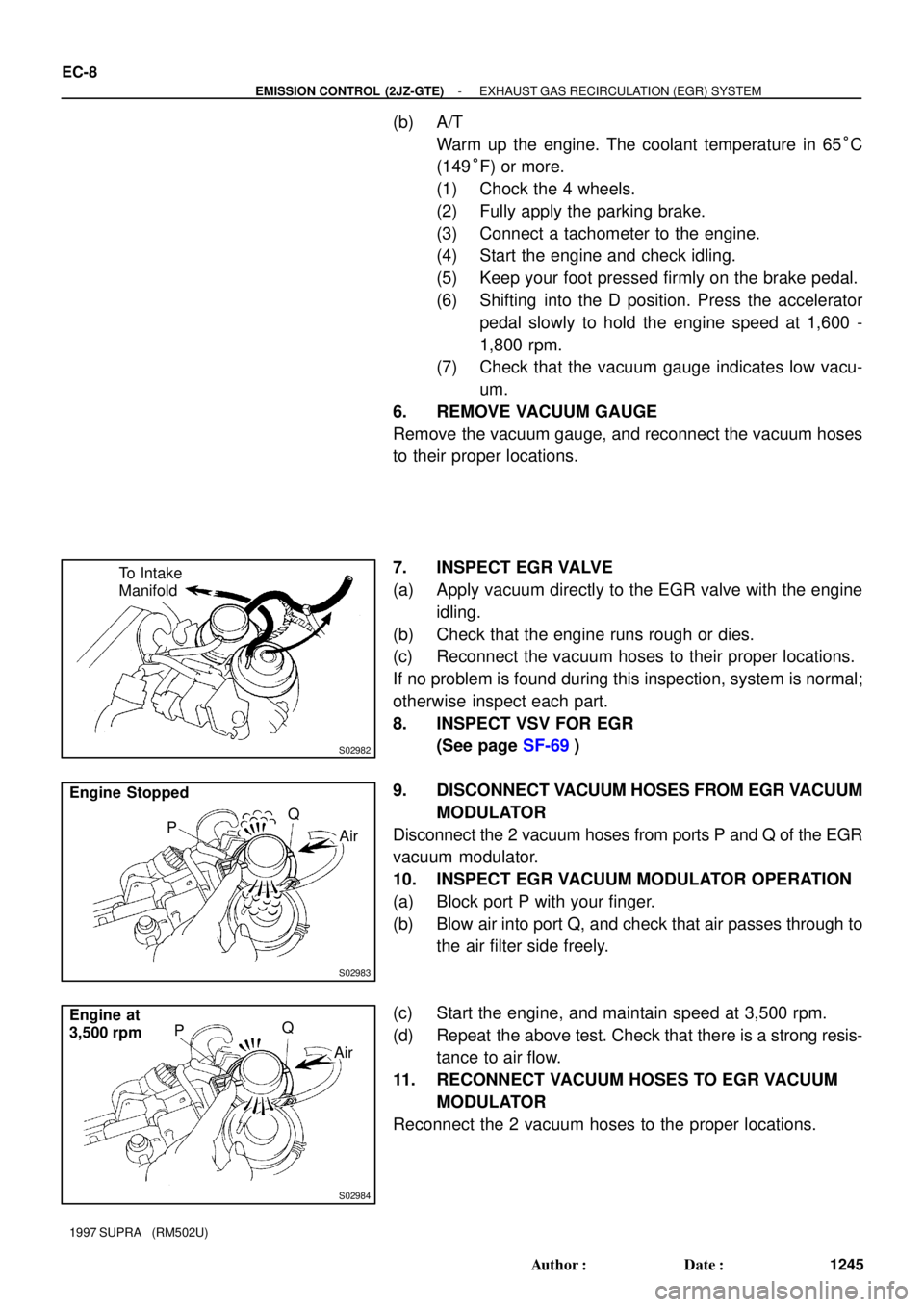
9. DISCONNECT VACUUM HOSES FROM EGR VACUUM
MODULATOR
Disconnect the 2 vacuum hoses from ports P and Q of the EGR
vacuum modulator.
10. INSPECT EGR VACUUM MODULATOR OPERATION
(a) Block port P with your finger.
(b) Blow air into port Q, and check that air passes through to
the air filter side freely.
(c) Start the engine, and maintain speed at 3,500 rpm.
(d) Repeat the above test. Check that there is a strong resis-
tance to air flow.
11. RECONNECT VACUUM HOSES TO EGR VACUUM
MODULATOR
Reconnect the 2 vacuum hoses to the proper locations.
Page 1282 of 1807
EM0AG-02
Z13597
Air Cleaner and
MAF Meter AssemblyNo.1 Air Hose
Engine Wire Protector
Air Cleaner Duct
Theft Deterrent Horn
Drive Belt
No.5 Air Hose
Hose Clamp
Oil Cooler Tube (A/T)
Hose Clamp
Front Lower Arm
Bracket Stay
Upper Crossmember
Extension
Engine Under CoverNo.2 Front Exhaust PipeHeat Insulator
Pipe Support BracketEVAP Hose
Brake Booster
Vacuum Hose
Tube Clamp
� Gasket
��� Gasket
x 16
� Non-reusable part
- ENGINE MECHANICAL (2JZ-GTE)CYLINDER HEAD
EM-25
1130 Author�: Date�:
1997 SUPRA (RM502U)
CYLINDER HEAD
COMPONENTS
Page 1284 of 1807

S05506
Sub-Throttle Position
Sensor Connector
Water Bypass Hose
PS Air Hose
� Gasket
Throttle Body
Throttle Position Sensor Connector
Sub-Throttle Actuator Connector
Control Cable
Bracket and Cable
Vacuum
Hose
Air
Hose
IAC Valve Pipe
Air Hose
Air Intake
Chamber Stay
IAC Valve
Connector Engine Wire Protector
VSV Connector for EGR
MAP Sensor Connector
VSV Connector for Fuel Pressure Control
Filler Cap
x 10 No.3 Timing Belt Cover
Ignition Coils AssemblyEVAP Hose
EGR Pipe
Engine Wire
Protector
Ground Cable
Brake Booster
Vacuum Hose
EGR Gas
Temperature
Sensor Connector
Vacuum Hose
Pressure Tank
and VSV Assembly
Engine Wire Bracket
Engine Wire Clamp
Manifold Stay� Gasket
x 5
No.4 Water Bypass Pipe PS Air Hose
No.4 Water
Bypass Hose
Water Bypass hose
Air Intake Chamber
Engine Wire Protector
� Gasket
Fuel Inlet Pipe
Fuel Pressure
Pulsation DamperVacuum Sensing Hose
Intake Manifold and
Delivery Pipe Assembly
Fuel Return Hose
� Gasket
x 6
� Gasket � Gasket
Engine Wire Bracket
PS Vane Pump
Oil Dipstick and
Guide for Transmission Oil Dipstick and
Guide for Engine
� O-Ring
� O-Ring
Timing Belt
Gasket
No.2 Timing
Belt Cover
Drive Belt Tensioner
Dust Cover
Timing Belt Tensioner
Drive Belt Tensioner Damper
� Non-reusable part
Drive Belt TensionerM/T
- ENGINE MECHANICAL (2JZ-GTE)CYLINDER HEAD
EM-27
1132 Author�: Date�:
1997 SUPRA (RM502U)
Page 1310 of 1807

EM0AV-02
P11544
(2)(3)
(1) EM-58
- ENGINE MECHANICAL (2JZ-GTE)ENGINE UNIT
1163 Author�: Date�:
1997 SUPRA (RM502U)
REMOVAL
1. REMOVE HOOD
2. REMOVE RADIATOR ASSEMBLY
(See page CO-22)
3. DRAIN ENGINE OIL
4. DRAIN FUEL FROM FUEL TANK
5. REMOVE NO.1 AIR HOSE
6. DISCONNECT CONTROL CABLES FROM
THROTTLE BODY
Disconnect these cables:
�Accelerator cable
�Cruise control actuator cable
7. REMOVE AIR CLEANER AND MAF METER
ASSEMBLY
(a) Remove the 3 bolts.
(b) Loosen the hose clamp, disconnect the air hose from the
intake air connector.
(c) Disconnect the MAF meter wire from the clamp on the air
cleaner case.
(d) Disconnect the MAF meter connector, and remove the air
cleaner and MAF meter assembly.
8. M/T:
REMOVE DRIVE BELT TENSIONER DAMPER
(See page EM-15)
9. REMOVE DRIVE BELT, FAN, FLUID COUPLING
ASSEMBLY AND WATER PUMP PULLEY
(See page CO-7)
10. REMOVE CHARCOAL CANISTER
11. DISCONNECT HEATER WATER HOSES
12. DISCONNECT BRAKE BOOSTER VACUUM HOSE
13. DISCONNECT EVAP HOSE
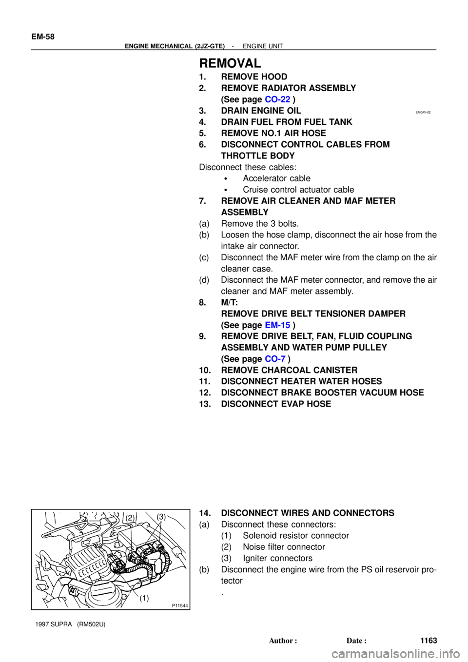
14. DISCONNECT WIRES AND CONNECTORS
(a) Disconnect these connectors:
(1) Solenoid resistor connector
(2) Noise filter connector
(3) Igniter connectors
(b) Disconnect the engine wire from the PS oil reservoir pro-
tector
.
Page 1321 of 1807

Z09735
B B
A
- ENGINE MECHANICAL (2JZ-GTE)ENGINE UNIT
EM-69
1174 Author�: Date�:
1997 SUPRA (RM502U)
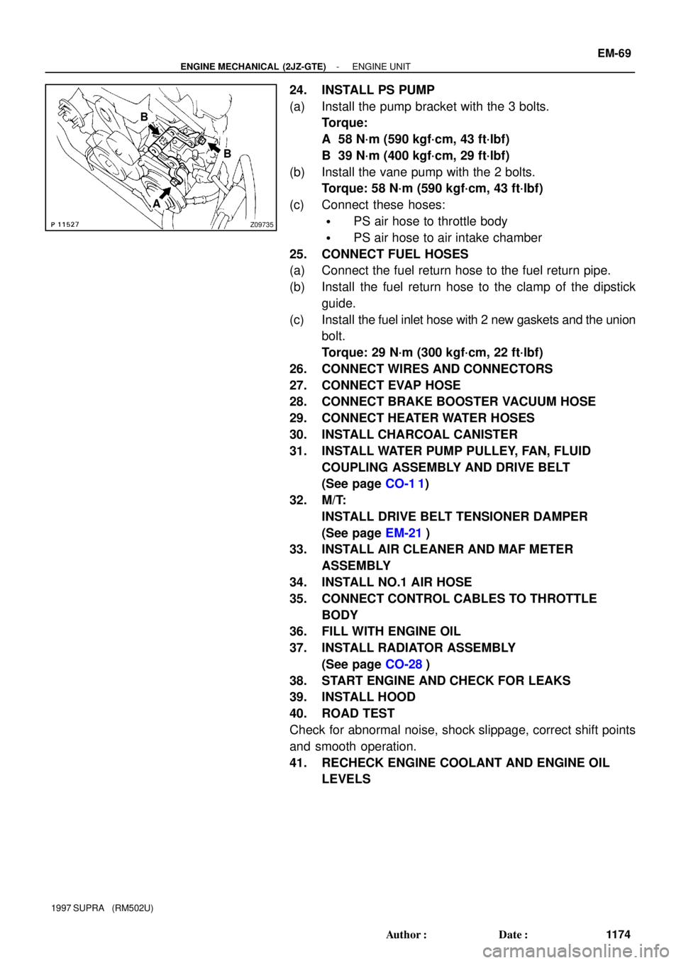
24. INSTALL PS PUMP
(a) Install the pump bracket with the 3 bolts.
Torque:
A 58 N´m (590 kgf´cm, 43 ft´lbf)
B 39 N´m (400 kgf´cm, 29 ft´lbf)
(b) Install the vane pump with the 2 bolts.
Torque: 58 N´m (590 kgf´cm, 43 ft´lbf)
(c) Connect these hoses:
�PS air hose to throttle body
�PS air hose to air intake chamber
25. CONNECT FUEL HOSES
(a) Connect the fuel return hose to the fuel return pipe.
(b) Install the fuel return hose to the clamp of the dipstick
guide.
(c) Install the fuel inlet hose with 2 new gaskets and the union
bolt.
Torque: 29 N´m (300 kgf´cm, 22 ft´lbf)
26. CONNECT WIRES AND CONNECTORS
27. CONNECT EVAP HOSE
28. CONNECT BRAKE BOOSTER VACUUM HOSE
29. CONNECT HEATER WATER HOSES
30. INSTALL CHARCOAL CANISTER
31. INSTALL WATER PUMP PULLEY, FAN, FLUID
COUPLING ASSEMBLY AND DRIVE BELT
(See page CO-1 1)
32. M/T:
INSTALL DRIVE BELT TENSIONER DAMPER
(See page EM-21)
33. INSTALL AIR CLEANER AND MAF METER
ASSEMBLY
34. INSTALL NO.1 AIR HOSE
35. CONNECT CONTROL CABLES TO THROTTLE
BODY
36. FILL WITH ENGINE OIL
37. INSTALL RADIATOR ASSEMBLY
(See page CO-28)
38. START ENGINE AND CHECK FOR LEAKS
39. INSTALL HOOD
40. ROAD TEST
Check for abnormal noise, shock slippage, correct shift points
and smooth operation.
41. RECHECK ENGINE COOLANT AND ENGINE OIL
LEVELS
Page 1350 of 1807

EM-2
- ENGINE MECHANICAL (2JZ-GTE)CO/HC
1107 Author�: Date�:
1997 SUPRA (RM502U)
If the CO/HC concentration does not comply with regulations,
troubleshoot in the order given below.
(1) Check heated oxygen sensors operation.
(See page SF-82)
(2) See the table below for possible causes, and then
inspect and correct the applicable causes if neces-
sary.
COHCPhenomenonCauses
NormalHighRough idle1. Faulty ignitions:
�Incorrect timing
�Fouled, shorted or improperly gapped plugs
2. Incorrect valve clearance
3. Leaky EGR valve
4.Leaky intake and exhaust valves
5.Leaky cylinder
LowHighRough idle
(Fluctuating HC reading)1. Vacuum leaks:
�PCV hose
�EGR valve
�Intake manifold
�Air intake chamber
�Throttle body
�IAC valve
�Brake booster line
2. Lean mixture causing misfire
HighHighRough idle
(Black smoke from exhaust)1. Restricted air filter:
2. Faulty SFI system:
�Faulty fuel pressure regulator
�Clogged fuel return line
�Defective ECT sensor
�Defective turbo pressure sensor
�Faulty ECM
�Faulty injector
�Faulty throttle position sensor
�Faulty MAF meter