Page 1654 of 1807

REMOVAL
1. REMOVE FRONT WHEEL
Torque: 103 N´m (1,050 kgf´cm, 76 ft�")
SA0PD-01
R00159
R07240
SST
R06928
- SUSPENSION AND AXLEFRONT LOWER SUSPENSION ARM
SA-33
1723 Author�: Date�:
1997 SUPRA (RM502U)
REMOVAL
1. REMOVE FRONT WHEEL
Torque: 103 N´m (1,050 kgf´cm, 76 ft´lbf)
2. REMOVE ENGINE UNDER COVER
3. REMOVE BRAKE CALIPER
(a) Remove the 2 bolts and brake caliper from the steering
knuckle.
Torque: 118 N´m (1,200 kgf´cm, 87 ft´lbf)
(b) Support the brake caliper securely.
4. DISCONNECT STABILIZER BAR LINK FROM SHOCK
ABSORBER BRACKET
Remove the nut and disconnect the stabilizer bar link from the
shock absorber bracket.
Torque: 74 N´m (750 kgf´cm, 54 ft´lbf)
HINT:
If the ball joint stud turns together with the nut, use a hexagon
wrench to hold the stud.
5. DISCONNECT STEERING KNUCKLE
(a) Remove the clip and nut.
Torque: 125 N´m (1,270 kgf´cm, 92 ft´lbf)
(b) Using SST, disconnect the steering knuckle from the low-
er suspension arm.
SST 09628-6201 1
6. REMOVE LOWER SUSPENSION ARM
(a) Remove the nut, washer and bolt and disconnect the low-
er suspension arm from the shock absorber.
Torque: 143 N´m (1,460 kgf´cm, 106 ft´lbf)
HINT:
At the time of installation, after stabilizing the suspension,
torque the nut.
(b) Remove the nut, 2 bolts and the lower suspension arm
bracket stay.
Bolt: 44 N´m (450 kgf´cm, 32 ft´lbf)
Nut: 59 N´m (600 kgf´cm, 43 ft´lbf)
HINT:
At the time of installation, before installing the lower suspension
arm bracket stay, adjust the front wheel alignment.
Page 1660 of 1807
SA0PK-02
W00616
Washer
Drive Shaft
Parking Brake CableBrake Caliper
Hub Bolt ABS Speed
SensorUpper Suspension Arm
Shoe Guide Plate
Lower Suspension
Arm No. 1Rear Shock
Absorber
Parking Brake
Exhaust Pipe Supprot
O-Ring Lower Suspension
Arm No. 2
Lower Suspension
Arm BraceStrut Rod
Exhaust PipeCotter Pin
Exhaust Pipe Supprot
RingDisc
Lock Cap
� Non-reusable part
- SUSPENSION AND AXLEREAR AXLE HUB
SA-41
1731 Author�: Date�:
1997 SUPRA (RM502U)
REAR AXLE HUB
COMPONENTS
Page 1662 of 1807

REMOVAL
1. REMOVE REAR WHEEL
Torque: 103 N´m (1,050 kgf´cm, 76 ft´lbf)
2. REMOVE BRAKE")
SA0PL-02
Z18437
R 1111 0
- SUSPENSION AND AXLEREAR AXLE HUB
SA-43
1733 Author�: Date�:
1997 SUPRA (RM502U)
REMOVAL
1. REMOVE REAR WHEEL
Torque: 103 N´m (1,050 kgf´cm, 76 ft´lbf)
2. REMOVE BRAKE CALIPER AND DISC
(a) Remove the 2 bolts and brake caliper from the rear axle
hub.
Torque: 104 N´m (1,065 kgf´cm, 77 ft´lbf)
(b) Support the brake caliper securely.
(c) Place matchmarks on the disc and axle hub.
(d) Remove the disc.
3. CHECK BEARING BACKLASH AND AXLE HUB DEVI-
ATION
(a) Using a dial indicator near the center of the axle hub and
check the backlash in the bearing shaft direction.
Maximum: 0.05 mm (0.0020 in.)
If the backlash exceeds the maximum, replace the bearing.
(b) Using a dial indicator, check the deviation at the surface
of the axle hub outside the hub bolt.
Maximum: 0.05 mm (0.0020 in.)
If the deviation exceeds the maximum, replace the axle hub.
4. REMOVE DRIVE SHAFT LOCK NUT
(a) Install the disc and brake caliper.
Torque: 104 N´m (1,065 kgf´cm, 77 ft´lbf)
(b) Remove the cotter pin and lock cap.
(c) With applying the brakes, remove the nut.
Torque: 289 N´m (2,950 kgf´cm, 213 ft´lbf)
(d) Remove the brake caliper and disc.
5. REMOVE DRIVE SHAFT (See page SA-51)
6. REMOVE PARKING BRAKE SHOE
(See page BR-60)
7. DISCONNECT ABS SPEED SENSOR
Remove the bolt and disconnect the ABS speed sensor.
Torque: 7.8 N´m (80 kgf´cm, 69 in.´lbf)
8. DISCONNECT PARKING BRAKE CABLE
(a) Remove the 2 parking brake cable set bolts.
Torque: 8.0 N´m (80 kgf´cm, 69 in.´lbf)
(b) Remove the 2 backing plate set bolts.
Torque: 26 N´m (260 kgf´cm, 19 ft´lbf)
(c) Remove the bolt and shoe guide plate.
Torque: 18 N´m (185 kgf´cm, 13 ft´lbf)
Page 1663 of 1807

(d) Using a 14 mm hexagon wrench, remove the hexagon
bolt.
Torque: 180 N´m (1,825")
R07043
R07312
Z09531
Matchmarks SA-44
- SUSPENSION AND AXLEREAR AXLE HUB
1734 Author�: Date�:
1997 SUPRA (RM502U)
(d) Using a 14 mm hexagon wrench, remove the hexagon
bolt.
Torque: 180 N´m (1,825 kgf´cm, 132 ft´lbf)
(e) Slide the backing plate to the outside and disconnect the
parking brake cable.
9. REMOVE STRUT ROD
Remove the 2 bolts and nuts.
Torque: 184 N´m (1,880 kgf´cm, 136 ft´lbf)
HINT:
At the time of installation, after stabilizing the suspension,
torque the bolt.
10. DISCONNECT LOWER SUSPENSION ARM NO.1
(a) Remove the 2 bolt and disconnect the parking brake
cable clamps.
Torque: 19 N´m (190 kgf´cm, 14 ft´lbf)
(b) Place matchmarks on the adjusting cam and sub-frame.
(c) Remove the nut, washer, adjusting cam plate and adjust-
ing cam and disconnect the lower suspension arm No.1.
Torque: 184 N´m (1,880 kgf´cm, 136 ft´lbf)
HINT:
At the time of installation, after stabilizing the suspension,
torque the nut.
11. DISCONNECT LOWER SUSPENSION ARM NO.2
(a) Remove the nut, washer and bolt and disconnect the
shock absorber from the lower suspension arm No.2.
Torque: 137 N´m (1,400 kgf´cm, 101 ft´lbf)
HINT:
At the time of installation, after stabilizing the suspension,
torque the nut.
(b) Remove the nut and disconnect the stabilizer bar link from
the lower suspension arm No.2.
Torque: 74 N´m (750 kgf´cm, 54 ft´lbf)
Page 1667 of 1807
Z04024
SSTSA0PP-01
Z04025
- SUSPENSION AND AXLEREAR WHEEL HUB BOLT
SA-49
1739 Author�: Date�:
1997 SUPRA (RM502U)
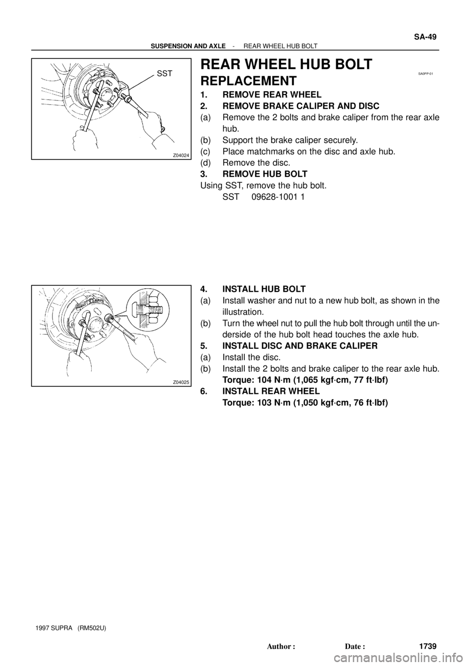
REAR WHEEL HUB BOLT
REPLACEMENT
1. REMOVE REAR WHEEL
2. REMOVE BRAKE CALIPER AND DISC
(a) Remove the 2 bolts and brake caliper from the rear axle
hub.
(b) Support the brake caliper securely.
(c) Place matchmarks on the disc and axle hub.
(d) Remove the disc.
3. REMOVE HUB BOLT
Using SST, remove the hub bolt.
SST 09628-1001 1
4. INSTALL HUB BOLT
(a) Install washer and nut to a new hub bolt, as shown in the
illustration.
(b) Turn the wheel nut to pull the hub bolt through until the un-
derside of the hub bolt head touches the axle hub.
5. INSTALL DISC AND BRAKE CALIPER
(a) Install the disc.
(b) Install the 2 bolts and brake caliper to the rear axle hub.
Torque: 104 N´m (1,065 kgf´cm, 77 ft´lbf)
6. INSTALL REAR WHEEL
Torque: 103 N´m (1,050 kgf´cm, 76 ft´lbf)
Page 1669 of 1807

REMOVAL
1. REMOVE REAR WHEEL
Torque: 103 N´m")
SA0PR-02
Z08967
TailpipeCenter Pipe
R07037
Matchmarks
R07024
R06937
- SUSPENSION AND AXLEREAR DRIVE SHAFT
SA-51
1741 Author�: Date�:
1997 SUPRA (RM502U)
REMOVAL
1. REMOVE REAR WHEEL
Torque: 103 N´m (1,050 kgf´cm, 76 ft´lbf)
2. DISCONNECT EXHAUST PIPE SUPPORTS
(a) Remove the 2 exhaust pipe support rings.
(b) Support the exhaust pipe securely.
(c) Remove the 2 exhaust pipe support O-rings.
3. REMOVE COTTER PIN, LOCK CAP AND LOCK NUT
(a) Remove the cotter pin and lock cap.
(b) With applying the brakes, remove the nut.
Torque: 289 N´m (2,950 kgf´cm, 213 ft´lbf)
4. REMOVE LOWER SUSPENSION ARM BRACE
Remove the 4 bolts and lower suspension arm brace.
Torque: 18 N´m (180 kgf´cm, 13 ft´lbf)
5. REMOVE REAR DRIVE SHAFT
(a) Place matchmarks on the drive shaft and side gear shaft.
(b) 2JZ-GE:
Using 8 mm hexagon wrench, remove the 6 hexagon
bolts and 3 washers with applying the brakes.
Torque: 68 N´m (695 kgf´cm, 50 ft´lbf)
(c) 2JZ-GTE:
Using a 10 mm hexagon wrench, remove the 6 hexagon
bolts and 2 washers with applying the brakes.
Torque: 83 N´m (850 kgf´cm, 61 ft´lbf)
(d) Disconnect the inboard joint from the differential side gear
shaft.
(e) Hold the inboard joint side of the drive shaft so that the
outboard joint side does not bend too much.
(f) Using a hammer, lightly tap the end of the drive shaft to
disengage the axle hub and remove the drive shaft.
NOTICE:
�Be careful not to damage the boots and speed sensor
rotor of the drive shaft, and oil seal of the axle hub.
�At the time of installation, make sure the outboard
joint side of the drive shaft does not bend too much.
Page 1705 of 1807
SA0Q4-02
R11047
Quarter Wheel House
Inner CoverInsulator
Shock
Absorber CapSuspension
Support
Spring Bumper
Coil Spring
Shock Absorber
with Coil SpringRear Shock
Absorber
Brake Caliper Stabilizer Bar
Link
Non-reusable part
- SUSPENSION AND AXLEREAR SHOCK ABSORBER
SA-89
1779 Author�: Date�:
1997 SUPRA (RM502U)
REAR SHOCK ABSORBER
COMPONENTS
Page 1706 of 1807

REMOVAL
1. w/ SPORT ROOF:
REMOVE THESE PARTS:
(See page BO-38)
�Rear seat cushion
�Rear seatba")
SA0Q5-01
R11102
SA-90
- SUSPENSION AND AXLEREAR SHOCK ABSORBER
1780 Author�: Date�:
1997 SUPRA (RM502U)
REMOVAL
1. w/ SPORT ROOF:
REMOVE THESE PARTS:
(See page BO-38)
�Rear seat cushion
�Rear seatback
�Tonneau cover retainer
�Holder garnish and holder
�Speaker grille
�Quarter trim board
2. REMOVE REAR WHEEL
Torque: 103 N´m (1,050 kgf´cm, 76 ft´lbf)
3. REMOVE REAR BRAKE CALIPER
(a) Remove the 2 bolts and brake caliper from the rear axle
carrier.
Torque: 104 N´m (1,065 kgf´cm, 77 ft´lbf)
(b) Support the brake caliper securely.
4. DISCONNECT REAR STABILIZER BAR LINK
Remove the nut and disconnect the stabilizer bar link from the
lower suspension arm No.2.
Torque: 74 N´m (750 kgf´cm, 54 ft´lbf)
5. REMOVE SHOCK ABSORBER WITH COIL SPRING
(a) Remove the nut and bolt on lower side of the shock ab-
sorber.
Torque: 137 N´m (1,400 kgf´cm, 101 ft´lbf)
HINT:
At the time of installation, after stabilizing the suspension,
torque the nut.
(b) Remove the quarter wheel house inner cover.
(c) Remove the 3 nuts and the shock absorber cap.
Torque: 10 N´m (105 kgf´cm, 8 ft´lbf)
(d) Loosen the nut in the middle of the suspension support.
NOTICE:
Do not remove the nut.
Torque: 27 N´m (280 kgf´cm, 20 ft´lbf)
(e) Remove the 3 nuts and shock absorber with the coil
spring.
Torque: 26 N´m (260 kgf´cm, 19 ft´lbf)