Page 1420 of 1807

MA01F-02
MA-4
- MAINTENANCEUNDER HOOD
41 Author�: Date�:
1997 SUPRA (RM502U)
UNDER HOOD
GENERAL MAINTENANCE
1. GENERAL NOTES
�Maintenance items may vary from country to country. Check the owner's manual supplement in which
the maintenance schedule is shown.
�Every service item in the periodic maintenance schedule must be performed.
�Periodic maintenance service must be performed according to whichever interval in the periodic main-
tenance schedule occurs first, the odometer reading (miles) or the time interval (months).
�Maintenance service after the last period should be performed at the same interval as before unless
otherwise noted.
�Failure to do even one item an cause the engine to run poorly and increase exhaust emissions.
2. WINDSHIELD WASHER FLUID
Check that there is sufficient fluid in the tank.
3. ENGINE COOLANT LEVEL
Check that the coolant level is between the ºFULLº and ºLOWº lines on the see-through reservoir.
4. RADIATOR AND HOSES
(a) Check that the front of the radiator is clean and not blocked with leaves, dirt or bugs.
(b) Check the hoses for cracks, kinks, rot or loose connections.
5. BATTERY ELECTROLYTE LEVEL
Check that the electrolyte level of all battery cells is between the upper and lower level lines on the case.
6. BRAKE AND CLUTCH FLUID LEVELS
Check that the brake and clutch fluid levels are near the upper level line on the see-through reservoirs.
7. ENGINE DRIVE BELT
Check drive belt for fraying, cracks, wear or oil contamination.
8. ENGINE OIL LEVEL
Check the level on the dipstick with the engine turned off.
9. POWER STEERING FLUID LEVEL
�Check the level on the dipstick.
�The level should be in the ºHOTº or ºCOLDº range depending on the fluid temperature.
10. AUTOMATIC TRANSMISSION FLUID LEVEL
(a) Park the vehicle on a level surface.
(b) With the engine idling and the parking brake applied, shift the selector into all positions from ºPº to ºLº,
and then shift into ºPº position.
(c) Pull out the dipstick and wipe off the fluid with a clean rag. Re-insert the dipstick and check that the
fluid level is in the HOT range.
(d) Do this check with the fluid at normal driving temperature (70 - 80°C, 158 - 176°F).
HINT:
Wait until the engine cools down (approx. 30 min.) before checking the fluid level after extended driving at
high speeds, in hot weather, in heavy traffic or pulling a trailer.
11. EXHAUST SYSTEM
If any change in the sound of the exhaust or smell of the exhaust fumes is noticed, have the cause located
and corrected.
Page 1422 of 1807

- MAINTENANCEINSIDE VEHICLE
MA-3
40 Author�: Date�:
1997 SUPRA (RM502U)
13. ACCELERATOR PEDAL
Check the pedal for smooth operation and uneven pedal effort or catching.
14. CLUTCH PEDAL (See page CL-3)
(a) Check the pedal for smooth operation.
(b) Check that the pedal has the proper freeplay.
15. BRAKE PEDAL (See page BR-7 )
(a) Check the pedal for smooth operation.
(b) Check that the pedal has the proper reserve distance and freeplay.
(c) Check the brake booster function.
16. BRAKES
At a safe place, check that the brakes do not pull to one side when applied.
17. PARKING BRAKE (See page BR-9)
(a) Check that the lever has the proper travel.
(b) On a safe incline, check that the vehicle is held securely with only the parking brake applied.
18. AUTOMATIC TRANSMISSION ºPARKº MECHANISM
(a) Check the lock release button of the selector lever for proper and smooth operation.
(b) On a safe incline, check that the vehicle is held securely with the selector lever in ºPº position and all
brakes released.
Page 1423 of 1807

B03050
MA01H-01
MA-6
- MAINTENANCEBRAKE
43 Author�: Date�:
1997 SUPRA (RM502U)
BRAKE
INSPECTION
1. INSPECT BRAKE LINE PIPES AND HOSES
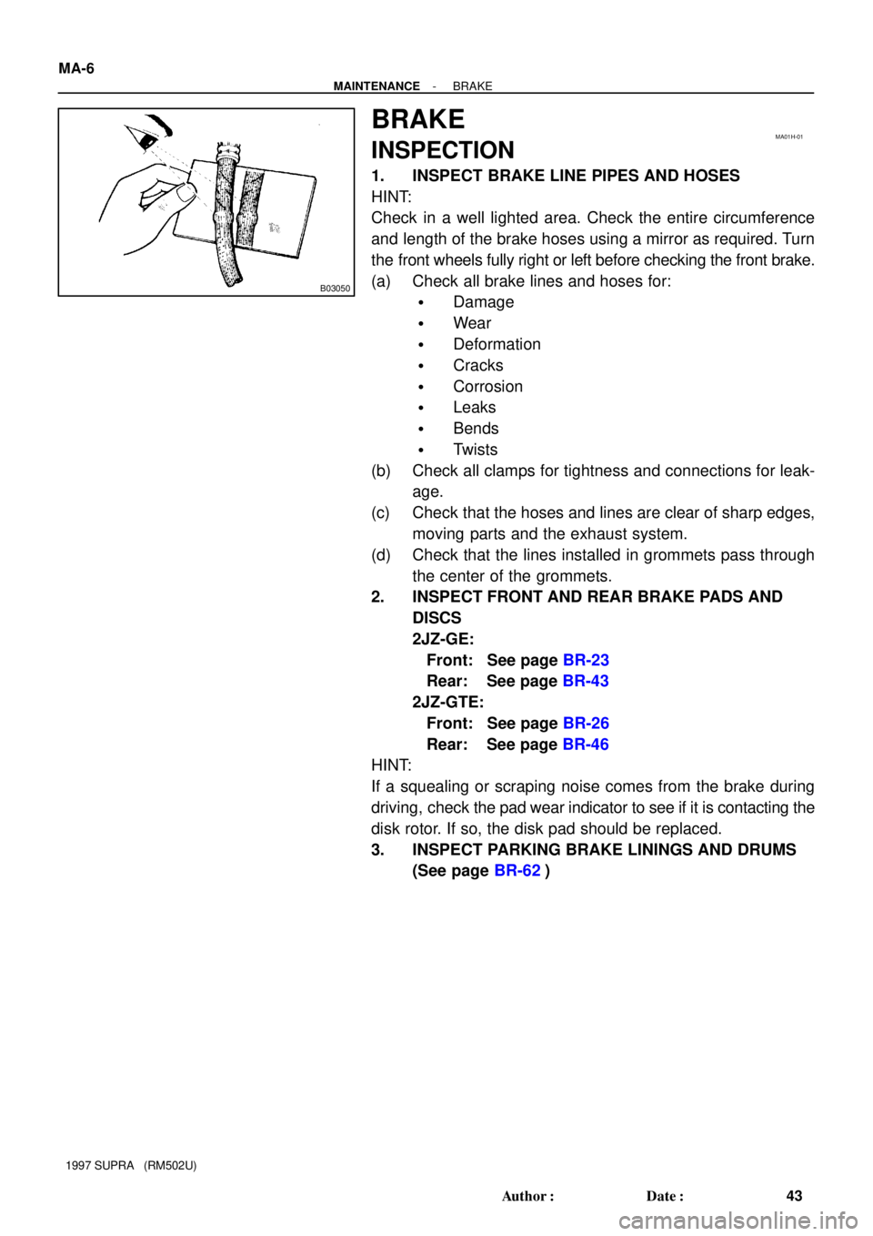
HINT:
Check in a well lighted area. Check the entire circumference
and length of the brake hoses using a mirror as required. Turn
the front wheels fully right or left before checking the front brake.
(a) Check all brake lines and hoses for:
�Damage
�Wear
�Deformation
�Cracks
�Corrosion
�Leaks
�Bends
�Twists
(b) Check all clamps for tightness and connections for leak-
age.
(c) Check that the hoses and lines are clear of sharp edges,
moving parts and the exhaust system.
(d) Check that the lines installed in grommets pass through
the center of the grommets.
2. INSPECT FRONT AND REAR BRAKE PADS AND
DISCS
2JZ-GE:
Front: See page BR-23
Rear: See page BR-43
2JZ-GTE:
Front: See page BR-26
Rear: See page BR-46
HINT:
If a squealing or scraping noise comes from the brake during
driving, check the pad wear indicator to see if it is contacting the
disk rotor. If so, the disk pad should be replaced.
3. INSPECT PARKING BRAKE LININGS AND DRUMS
(See page BR-62)
Page 1425 of 1807

B03052
37 N´m
B03053
200 N´m
125 N´m
B03054
58 N´m
175 N´m
MA01J-01
MA-8
- MAINTENANCEBODY
45 Author�: Date�:
1997 SUPRA (RM502U)
BODY
INSPECTION
1. TIGHTEN BOLTS AND NUTS ON CHASSIS AND
BODY
Tighten these parts:
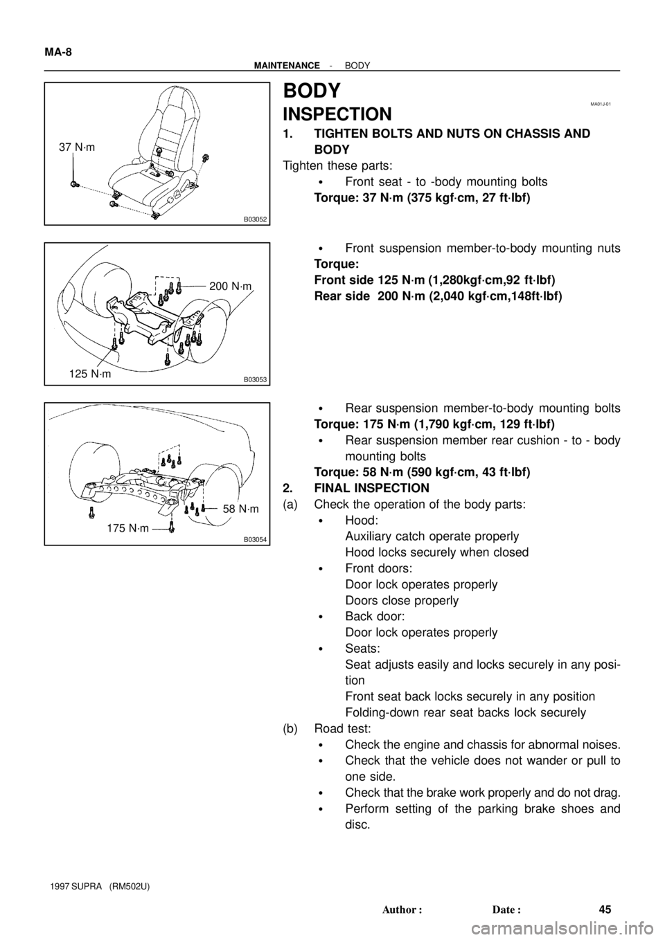
�Front seat - to -body mounting bolts
Torque: 37 N´m (375 kgf´cm, 27 ft´lbf)
�Front suspension member-to-body mounting nuts
Torque:
Front side 125 N´m (1,280kgf´cm,92 ft´lbf)
Rear side 200 N´m (2,040 kgf´cm,148ft´lbf)
�Rear suspension member-to-body mounting bolts
Torque: 175 N´m (1,790 kgf´cm, 129 ft´lbf)
�Rear suspension member rear cushion - to - body
mounting bolts
Torque: 58 N´m (590 kgf´cm, 43 ft´lbf)
2. FINAL INSPECTION
(a) Check the operation of the body parts:
�Hood:
Auxiliary catch operate properly
Hood locks securely when closed
�Front doors:
Door lock operates properly
Doors close properly
�Back door:
Door lock operates properly
�Seats:
Seat adjusts easily and locks securely in any posi-
tion
Front seat back locks securely in any position
Folding-down rear seat backs lock securely
(b) Road test:
�Check the engine and chassis for abnormal noises.
�Check that the vehicle does not wander or pull to
one side.
�Check that the brake work properly and do not drag.
�Perform setting of the parking brake shoes and
disc.
Page 1458 of 1807
RS070-02
- SUPPLEMENTAL RESTRAINT SYSTEMAIRBAG SENSOR ASSEMBLY
RS-33
1972 Author�: Date�:
1997 SUPRA (RM502U)
REMOVAL
NOTICE:
Do not open the cover or the case of the ECU and various
electrical devices unless absolutely necessary.
(If the IC terminals are touched, the IC may be destroyed by
static electricity.)
1. REMOVE THESE PARTS
(a) Console panel upper
(b) Parking brake hole cover
(c) Console box
2. REMOVE AIRBAG SENSOR ASSEMBLY
(a) Disconnect the airbag sensor connectors.
NOTICE:
Remove the connectors with the sensor assembly
installed.
(b) Using a torx wrench, remove the 4 screws and airbag sen-
sor assembly.
Torx wrench: T40 (Part No.09042-00020 or locally
manufactured tool)
Page 1459 of 1807

RS073-02
RS-36
- SUPPLEMENTAL RESTRAINT SYSTEMAIRBAG SENSOR ASSEMBLY
1975 Author�: Date�:
1997 SUPRA (RM502U)
INSTALLATION
NOTICE:
�Never use SRS parts from another vehicle. When re-
placing parts, replace them with new parts.
�Never reuse the airbag sensor assembly involved in
a collision when the airbag has deployed.
�Never repair a sensor in order to reuse it.
1. INSTALL AIRBAG SENSOR ASSEMBLY
(a) Using a torx wrench, install the airbag sensor assembly
with 4 screws.
Torx wrench: T40 (Part No.09042-00020 or locally
manufactured tool)
Torque: 21 N´m (210 kgf´cm, 15 ft´lbf)
(b) Connect the airbag sensor connectors.
NOTICE:
�Installation of the connector is done after the sensor
assembly has been installed.
�Make sure the sensor assembly is installed with the
specified torque.
�If the sensor assembly has been dropped, or there are
cracks, dents or other defects in the case, bracket or
connector, replace the sensor assembly with a new
one.
�When installing the senor assembly, take care that
the SRS wiring does not interfere with other parts and
is not pinched between other parts.
�After installing , shake the sensor assembly to check
that there is no looseness.
2. INSTALL THESE PARTS:
(a) Console box
(b) Parking brake hole cover
(c) Console panel upper
Page 1463 of 1807

P12822
Plug
P12089
New
Gasket
FI1654
Fulcrum Length
30 cm
SST
P11303
New
O-Ring
New
Insulator
P12837
Delivery Pipe
O-Ring
Insulator
Intake
ManifoldInjector
Holder
Injector
SpacerInsulator
- SFI (2JZ-GTE)SFI SYSTEM
SF-3
1329 Author�: Date�:
1997 SUPRA (RM502U)
(3) Put a container under the connection.
(4) Slowly loosen the connection.
(5) Disconnect the connection.
(6) Plug the connection with a rubber plug.
(7) Reconnect the fuel pump connector.
(b) When connecting the flare nut or union bolt on the high
pressure pipe union, observe the following procedures:
(1) Union Bolt Type:
Always use a new gasket.
(2) Union Bolt Type:
Tighten the union bolt by hand.
(3) Union Bolt Type:
Tighten the union bolt to the specified torque.
Torque: 29 N´m (300 kgf´cm, 22 ft´lbf)
(4) Flare Nut Type:
Apply a light coat of engine oil to the flare nut and
tighten the flare nut by hand.
(5) Flare Nut Type:
Using SST, tighten the flare nut to the specified
torque.
SST 09631-22020
Torque: 30 N´m (310 kgf´cm, 22 ft´lbf)
HINT:
Use a torque wrench with a fulcrum length of 30 cm (11.81 in.).
(c) Observe the following precautions when removing and
installing the injectors.
(1) Never reuse the O-ring.
(2) When placing a new O-ring on the injector, take
care not to damage it in any way.
(3) Coat a new O-ring with spindle oil or gasoline be-
fore installing-never use engine, gear or brake oil.
(d) Install the injector to the delivery pipe and intake manifold
as shown in the illustration.
Page 1478 of 1807

SF0GR-01
S04780
Engine Wire
Protector
Air Intake Chamber Stay
IAC Valve Connector
VSV Connector for EGR
Turbo Pressure Sensor Connector
VSV Connector for Fuel Pressure Control
Water Bypass HoseControl Cable Bracket and Cable
Vacuum HoseIAC Valve Pipe
EVAP Hose
� Gasket
EGR Pipe
Brake Booster
Vacuum Hose
Engine
Wire
Protector
Engine Wire Bracket
Engine Wire ClampGround
Cable
EGR Gas Temperature
Sensor Connector
Manifold Stay
No.4 Water Bypass Pipe
Water Bypass Hose Air Intake
Chamber
PS Air Hose Injector Connector
Engine Wire
Clamp
� InsulatorInjector � O - Ring
Vacuum Sensing Hose
Spacer
Delivery Pipe
Fuel Return Pipe
Sub-Throttle Position
Sensor ConnectorInjector Holder
x3
Fuel Inlet Pipe
PCV Hose
Oil Dipstick and Guide for A/T � Gasket
� Gasket
Air Hose
PS Air Hose
Water Bypass Hose
Sub - Throttle Actuator
Connector
Engine Under Cover � Gasket � Insulator
Spacer
Fuel Return Hose Throttle Body
Throttle Position
Sensor ConnectorOil Dipstick and Guide
for Engine� O - Ring
� O - Ring � Gasket
� Gasket
� Non - reusable part
- SFI (2JZ-GTE)INJECTOR
SF-19
1345 Author�: Date�:
1997 SUPRA (RM502U)
COMPONENTS