Page 1480 of 1807

(2)
(3) Clamp
P11318(4)
(5)
S04464
(10)
(8)
(6)(7)(9) (11)
S04463
EGR Gas
Temperature
Sensor
Connector
EGR Pipe
- SFI (2JZ-GTE)INJECTOR
SF-21
1347 Author�: Date�:
1997 SUPRA (RM502")
P11991
P11317
(1)
(2)
(3) Clamp
P11318(4)
(5)
S04464
(10)
(8)
(6)(7)(9) (11)
S04463
EGR Gas
Temperature
Sensor
Connector
EGR Pipe
- SFI (2JZ-GTE)INJECTOR
SF-21
1347 Author�: Date�:
1997 SUPRA (RM502U)
(b) Remove the bolt, and disconnect the engine wire protec-
tor from the body.
(c) Disconnect these hoses:
(1) Air hose from IAC valve
Disconnect the IAC valve pipe from the clamp on
the cylinder head cover, and disconnect the air hose
from the IAC valve.
(2) Air hose (from air intake chamber) from
vacuum pipe on IAC valve pipe
(3) Air hose for EGR from valve pipe
(4) PCV hose from PCV valve
(5) Vacuum sensing hose from fuel pressure
regulator
(6) Water bypass hose (from IAC valve) from No.4 wa-
ter bypass pipe
(7) EVAP hose (from air intake chamber) from
vacuum pipe on manifold stay
(8) EVAP hose (from vacuum pipe on No.4 water
bypass pipe) from No.2 vacuum pipe
(9) EVAP hose (from charcoal canister) from No.2
vacuum pipe
(10) PS air hose from air intake chamber
(11) Brake booster vacuum hose from union on air in-
take chamber
8. DISCONNECT EGR GAS TEMPERATURE SENSOR
CONNECTOR
(a) Disconnect the connector from the No.2 vacuum pipe.
(b) Disconnect the sensor connector from the wiring connec-
tor.
9. REMOVE EGR PIPE
(a) Remove the union bolt holding the EGR pipe to the EGR
valve.
Torque: 64 N´m (650 kgf´cm, 47 ft´lbf)
Page 1541 of 1807
SF0IC-02
Q08242
TOYOTA Hand-Held Tester
DLC3
P11358Sound Scope
- SFI (2JZ-GTE)FUEL CUT RPM
SF-87
1413 Author�: Date�:
1997 SUPRA (RM502U)
FUEL CUT RPM
INSPECTION
1. WARM UP ENGINE
Allow the engine to warm up to normal operating temperature.
2. CONNECT TOYOTA HAND-HELD TESTER OR
OBDII SCAN TOOL
(a) Connect the TOYOTA hand-held tester or OBDII scan
tool to the DLC3.
(b) Please refer to the TOYOTA hand-held tester or
OBDII scan tool operator's manual for further details.
3. INSPECT FUEL CUTOFF OPERATION
(a) Increase the engine speed to at least 3,000 rpm.
(b) Check for injector operating noise.
(c) Check that when the throttle lever is released, injector op-
eration noise stops momentarily and then resumes.
HINT:
Measure with the A/C OFF.
Fuel return speed:
1,400 rpm
(Vehicle speed less than 25 km/h (16 mph), with brake
OFF)
4. DISCONNECT TOYOTA HAND-HELD TESTER OR
OBDII SCAN TOOL
Page 1581 of 1807
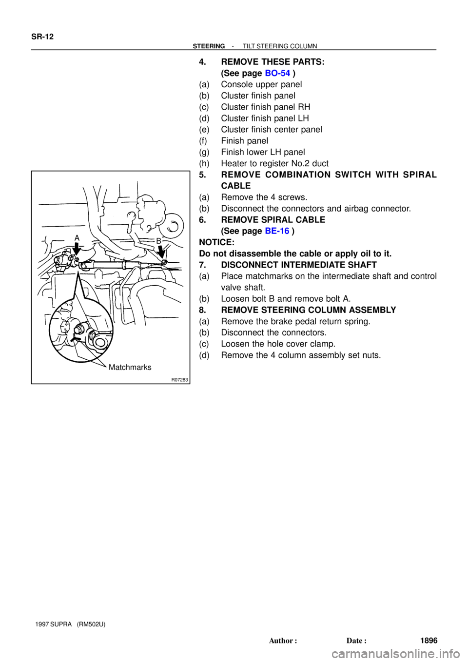
R07283
A
B
Matchmarks SR-12
- STEERINGTILT STEERING COLUMN
1896 Author�: Date�:
1997 SUPRA (RM502U)
4. REMOVE THESE PARTS:
(See page BO-54)
(a) Console upper panel
(b) Cluster finish panel
(c) Cluster finish panel RH
(d) Cluster finish panel LH
(e) Cluster finish center panel
(f) Finish panel
(g) Finish lower LH panel
(h) Heater to register No.2 duct
5. REMOVE COMBINATION SWITCH WITH SPIRAL
CABLE
(a) Remove the 4 screws.
(b) Disconnect the connectors and airbag connector.
6. REMOVE SPIRAL CABLE
(See page BE-16)
NOTICE:
Do not disassemble the cable or apply oil to it.
7. DISCONNECT INTERMEDIATE SHAFT
(a) Place matchmarks on the intermediate shaft and control
valve shaft.
(b) Loosen bolt B and remove bolt A.
8. REMOVE STEERING COLUMN ASSEMBLY
(a) Remove the brake pedal return spring.
(b) Disconnect the connectors.
(c) Loosen the hole cover clamp.
(d) Remove the 4 column assembly set nuts.
Page 1590 of 1807

INSTALLATION
1. INSTALL STEERING COLUMN ASSEMBLY
(a) Torque the 4")
SR142-01
W02982
R07283
Matchmarks A
B
R05740
Red Mark
- STEERINGTILT STEERING COLUMN
SR-21
1905 Author�: Date�:
1997 SUPRA (RM502U)
INSTALLATION
1. INSTALL STEERING COLUMN ASSEMBLY
(a) Torque the 4 column assembly set nuts.
Torque: 25 N´m (260 kgf´cm, 19 ft´lbf)
(b) Connect the connectors.
(c) Install the brake pedal return spring.
(d) Tighten the hole cover clamp.
2. CONNECT INTERMEDIATE SHAFT
(a) Align the matchmarks on the intermediate shaft and con-
trol valve shaft.
(b) Torque the bolt A.
Torque: 35 N´m (360 kgf´cm, 26 ft´lbf)
(c) Torque the bolt B.
Torque: 35 N´m (360 kgf´cm, 26 ft´lbf)
3. INSTALL SPIRAL CABLE
(See page BE-16)
4. INSTALL COMBINATION SWITCH WITH SPIRAL
CABLE
(a) Tighten the 4 screws.
(b) Connect the connectors and airbag connector.
5. INSTALL THESE PARTS:
(See page BO-59)
(a) Heater to Register No.2 duct
(b) Finish lower LH panel
(c) Finish panel
(d) Cluster finish center panel
(e) Cluster finish panel LH
(f) Cluster finish panel RH
(g) Cluster finish panel
(h) Console upper panel
6. INSTALL COLUMN UPPER AND LOWER COVERS
Tighten the 5 screws.
7. CENTER SPIRAL CABLE
(a) Check that the front wheels are facing straight ahead.
(b) Turn the spiral cable counterclockwise by hand until it be-
comes harder to turn the cable.
(c) Rotate the spiral cable clockwise about 3 turns to align the
marks.
HINT:
The spiral cable will rotate about 3 turns to either left or right of
the center.
Page 1632 of 1807

REAR WHEEL ALIGNMENT
INSPECTIO")
SA0OS-02
SA3213
AB
D
Front
C
R05816R05817F03229
LH
RHA
E = B - AB
C
D
F = D - C SA-8
- SUSPENSION AND AXLEREAR WHEEL ALIGNMENT
1698 Author�: Date�:
1997 SUPRA (RM502U)
REAR WHEEL ALIGNMENT
INSPECTION
1. MEASURE REAR VEHICLE HEIGHT
(See page SA-3)
2. INSTALL CAMBER- CASTER- KINGPIN GAUGE
ONTO VEHICLE OR POSITION VEHICLE ON WHEEL
ALIGNMENT TESTER
Follow the specific instructions of the equipment manufacturer.
3. INSPECT CAMBER
2JZ-GE2JZ-GTE
Camber
Left-right error-1°35' ± 45'
(-1.58° ± 0.75°)
30' (0.5°) or less-1°30' ± 45'
(-1.5° ± 0.75°)
30' (0.5°) or less
4. INSPECT TOE-IN
Toe-in
(Total)A + B: 0°18' ± 12' (0.3° ± 0.2°)
C - D: 3 ± 2 mm (0.12 ± 0.08 in.)
5. ADJUST CAMBER AND TOE-IN
(a) Measure the length of the lower suspension arm No.1 and
No.2, as shown in the illustration.
Length:
(E - F) or (F - E) should be less than 4.0 mm (0.16 in.).
If not, adjust the length of the arms by turning the adjusting cam
as shown, until (E - F) or (F - E) is less than 4.0 mm (0.16 in.).
(b) Measure the camber and toe-in.
If the camber and toe-in are still not within the specification, ad-
just the camber and toe-in with the adjusting cam.
(c) Remove the bolt and disconnect the parking brake cable
bracket.
Page 1633 of 1807
R06947
Z18438
Example
Camber
Toe-in
R05675
Front
LHRH + (Longer) - (Shorter) - (Shorter)
- (Shorter) - (Shorter) + (Longer) + (Longer)+ (Longer)
- SUSPENSION AND AXLEREAR WHEEL ALIGNMENT
SA-9
1699 Author�: Date�:
1997 SUPRA (RM502U)
(d) Loosen and adjust the No.1 and/or No.2 cams.
(e) Adjust camber and toe-in by turning the No.1 and/or No.2
cams (See adjustment chart).
HINT:
Try to adjust the camber and toe-in to the center value.
(f) Torque the No.1 and/or No.2 cam nuts.
Torque: 184 N´m (1,880 kgf´cm, 136 ft´lbf)
(g) Connect the parking brake cable bracket with the bolt.
6. HOW TO READ ADJUSTMENT CHART
(a) Mark on the graph the measurements taken from vehicle.
Example (2JZ-GTE):
Camber (LH): -1°00' (-1°)
Camber (RH): -1°30' (-1.5°)
(b) Read from the graph the amounts of the front and/or rear
cam to be adjusted.
Amount to turn adjusting cam (by graduation)
LH Front cam: + (Longer) 1.1
LH Rear cam: + (Longer) 3.0
RH Front cam: - (Shorter) 1.0
RH Rear cam: + (Longer) 0.9
Page 1635 of 1807
SA0OT-02
R11037
Steering
Knuckle with
Axle Hub
Cotter Pin
Brake Caliper
Hub Bolt
Brake Dust Cover
Axle Hub Oil Seal Snap Ring Bearing
Steering Knuckle ABS Speed
Sensor RotorGrease CapTie Rod End ABS Speed Sensor
� Cotter PinClip
Disc
Non-reusable part
- SUSPENSION AND AXLEFRONT AXLE HUB
SA-1 1
1701 Author�: Date�:
1997 SUPRA (RM502U)
FRONT AXLE HUB
COMPONENTS
Page 1636 of 1807

REMOVAL
1. REMOVE FRONT WHEEL
Torque: 103 N´m (1,050 kgf´cm, 76 ft´lbf)
2. REMOVE BRA")
SA0OU-02
R11096
SA3535SST SA-12
- SUSPENSION AND AXLEFRONT AXLE HUB
1702 Author�: Date�:
1997 SUPRA (RM502U)
REMOVAL
1. REMOVE FRONT WHEEL
Torque: 103 N´m (1,050 kgf´cm, 76 ft´lbf)
2. REMOVE BRAKE CALIPER AND DISC
(a) Remove the 2 bolts and brake caliper from the steering
knuckle.
Torque: 118 N´m (1,200 kgf´cm, 87 ft´lbf)
(b) Support the brake caliper securely.
(c) Place matchmarks on the disc and axle hub.
(d) Remove the disc.
3. CHECK BEARING BACKLASH AND AXLE HUB DEVI-
ATION
(a) Using a dial indicator near the center of the axle hub and
check the backlash in the bearing shaft direction.
Maximum: 0.05 mm (0.0020 in.)
If the backlash exceeds the maximum, replace the bearing.
(b) Using a dial indicator, check the deviation at the surface
of the axle hub outside the hub bolt.
Maximum: 0.05 mm (0.0020 in.)
If the deviation exceeds the maximum, replace the bearing.
4. DISCONNECT ABS SPEED SENSOR FROM STEER-
ING KNUCKLE
Remove the bolt and disconnect the ABS speed sensor from
the steering knuckle.
Torque: 7.8 N´m (80 kgf´cm, 69 in.´lbf)
5. DISCONNECT TIE ROD END FROM STEERING
KNUCKLE
(a) Remove the cotter pin and nut.
Torque: 49 N´m (500 kgf´cm, 36 ft´lbf)
(b) Using SST, disconnect the tie rod end from the steering
knuckle.
SST 09611-12010

 - (Shorter) - (Shorter)
 + (Longer) + (Longer)+ (Longer)
- SUSPENSION AND AXLEREAR WHEEL ALIGNMENT
SA-9
1699 Au")
