Page 978 of 1807

N19613
22
1 2
4
3
10 16Cruise Control ECU
1B
I1 S11
S11G-W
B-W
Cruise Control Actuator R/B No.2
Battery
B 2A2
ALT
W-LJ/B No.1
STOP10
C16
L STP-
2 W-L
S11 S11
C16
POWERR-LR-LWStop Light Switch
- DIAGNOSTICSCRUISE CONTROL SYSTEM
DI-687
915 Author�: Date�:
1997 SUPRA (RM502U)
Stop Light Switch Circuit
CIRCUIT DESCRIPTION
When the brake is on, battery positive voltage normally applies through the STOP fuse and stop light switch
to terminal STP- of the ECU, and the ECU turns the cruise control off.
A fail-safe function is provided so that cancel functions normally, even if there is a malfunction in the stop
light signal circuit.
If the harness connected to terminal STP- has an open circuit, terminal STP- will have battery positive volt-
age and the cruise control will be turned off.
Also, when the brake is on, the magnetic clutch is cut mechanically by the stop light switch, turning the cruise
control off. (See page DI-675 for operation of the magnetic clutch)
WIRING DIAGRAM
DI4XX-01
Page 979 of 1807
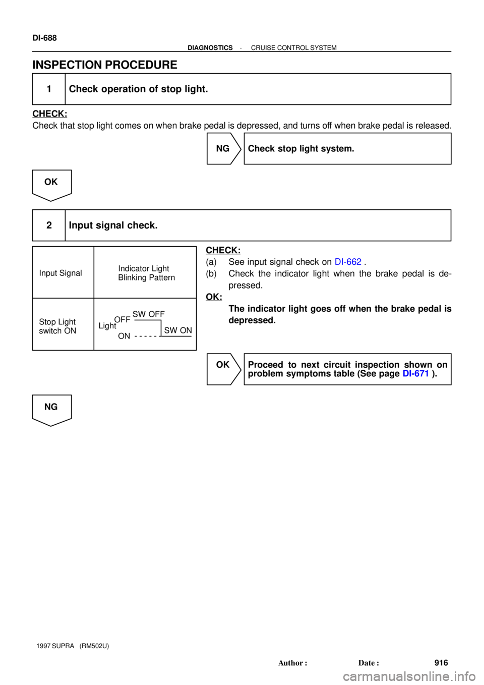
Input SignalIndicator Light
Blinking Pattern
Stop Light
switch ON
LightOFF
ONSW OFF
SW ON
DI-688
- DIAGNOSTICSCRUISE CONTROL SYSTEM
916 Author�: Date�:
1997 SUPRA (RM502U)
INSPECTION PROCEDURE
1 Check operation of stop light.
CHECK:
Check that stop light comes on when brake pedal is depressed, and turns off when brake pedal is released.
NG Check stop light system.
OK
2 Input signal check.
CHECK:
(a) See input signal check on DI-662.
(b) Check the indicator light when the brake pedal is de-
pressed.
OK:
The indicator light goes off when the brake pedal is
depressed.
OK Proceed to next circuit inspection shown on
problem symptoms table (See page DI-671).
NG
Page 980 of 1807
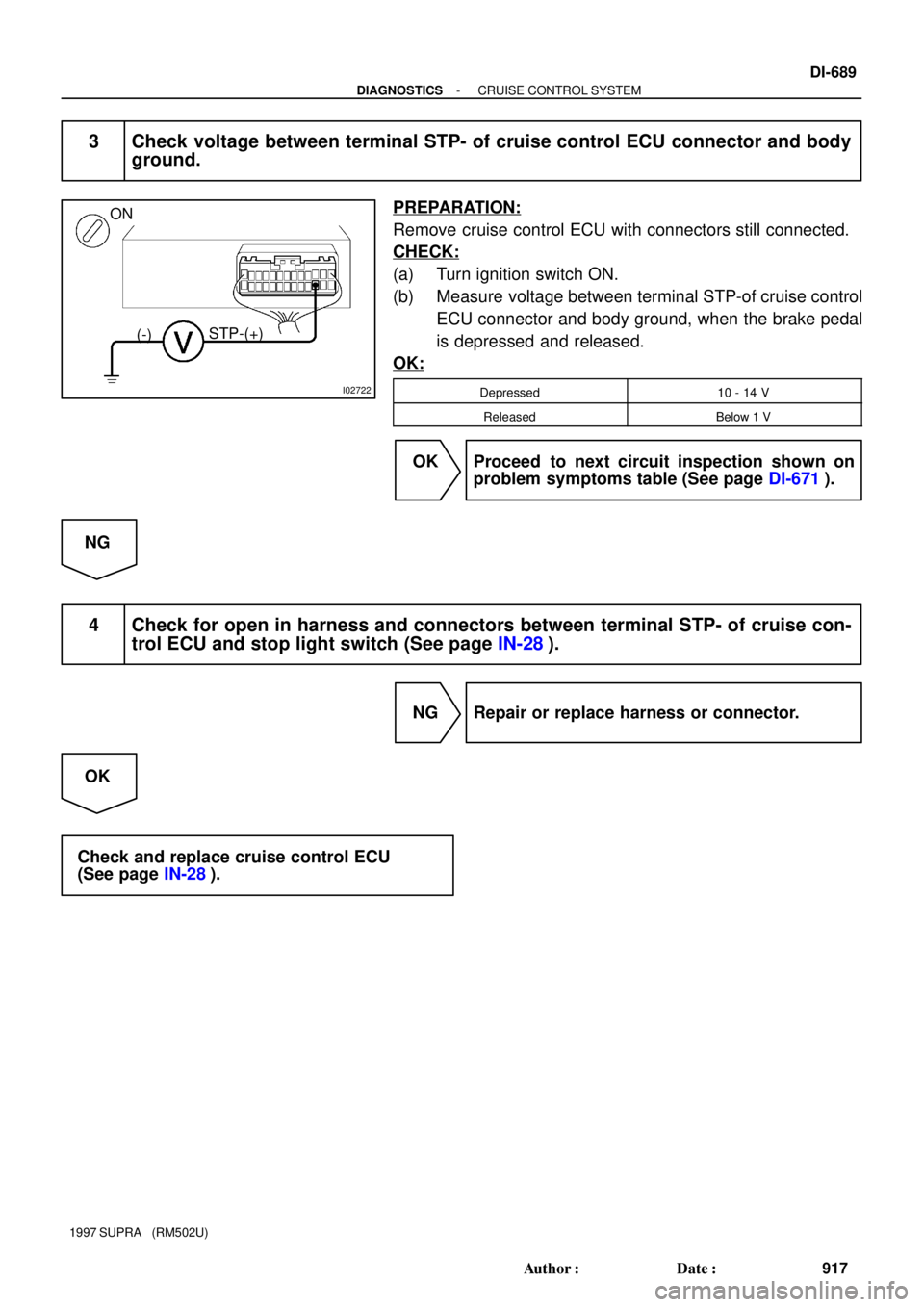
I02722
ON
(-)STP-(+)
- DIAGNOSTICSCRUISE CONTROL SYSTEM
DI-689
917 Author�: Date�:
1997 SUPRA (RM502U)
3 Check voltage between terminal STP- of cruise control ECU connector and body
ground.
PREPARATION:
Remove cruise control ECU with connectors still connected.
CHECK:
(a) Turn ignition switch ON.
(b) Measure voltage between terminal STP-of cruise control
ECU connector and body ground, when the brake pedal
is depressed and released.
OK:
Depressed10 - 14 V
ReleasedBelow 1 V
OK Proceed to next circuit inspection shown on
problem symptoms table (See page DI-671).
NG
4 Check for open in harness and connectors between terminal STP- of cruise con-
trol ECU and stop light switch (See page IN-28).
NG Repair or replace harness or connector.
OK
Check and replace cruise control ECU
(See page IN-28).
Page 1015 of 1807
16
ABBREVIATIONS D
ABBREVIATIONS
The follow abbreviations are used in this manual.
ABS = Anti-Lock Brake Systerm O/D = Overdrive
A/C = Air Conditioning PPS = Progressive Power Steering
ACIS = Acoustic Control Induction System R/B = Relay Block
A/T = Automatic Transmission RH = Right-Hand
COMB. = Combination SFI = Sequential Multiport Fuel Injection
ECU. = Electronic Control Unit SRS = Supplemental Restraint System
EGR = Exhaust Gas Recirculation SW = Switch
ESA = Electronic Spark Advance TEMP. = Temperature
EVAP = Evaporative Emission TRAC = Traction Control
J/B = Junction Block VSV = Vacuum Switching Valve
LH = Left-Hand w/ = With
M/T = Manual Transmission w/o = Without
* The titles given inside the components are the names of the terminals (terminal codes) and are not treated
as being abbreviations.
Page 1024 of 1807

Position of Parts in Engine Compartment
E 4 Engine Coolant Temp. Sender
E 5 Engine Coolant Temp. SW
E 6 Engine Hood Courtesy SW
E 7 Engine Oil Level Sensor
F 3 Front Fog Light LH
F 4 Front Fog Light RH
F 5 Front Side Marker Light LH
F 6 Front Side Marker Light RH
F 7 Front Turn Signal Light LH
F 8 Front Turn Signal Light RH and Parking Light RH
F 9 Front Wiper Motor
G 1 Generator
G 2 Generator
H 1 Headlight Hi LH
H 2 Headlight Hi RH
H 3 Headlight Lo LH
H 4 Headlight Lo RH
H 5 Heated Oxygen Sensor (Bank 1 Sensor 1)
H 8 Horn LH
H 9 Horn RH A 1 A/C Ambient Temp Sensor
A 2 A/C Condensor Fan Motor
A 3 A/C Triple Pressure SW
(A/C Dual and Single Pressure SW)
A 4 A/C Magnetic Clutch and Lock Sensor
A 5 A/T Fluid Temp. Sensor
A 6 ABS Actuator
A 7 ABS Actuator
A10 ABS Speed Sensor Front LH
A11 ABS Speed Sensor Front RH
B 1 Back-Up Light SW (M/T)
B 2 Brake Fluid Level Warning SW
C 1 Camshaft Position Sensor No.1
C 2 Camshaft Position Sensor No.2
C 3 Crankshaft Position Sensor
C 4 Cruise Control Actuator
D 1 Data Link Connector 1
D 2 Daytime Running Light Relay No.3
D 3 Daytime Running Light Relay No.3
E 1 EGR Gas Temp. Sensor
E 2 Electronically Controlled Transmission Solenoid
E 3 Engine Coolant Temp. Sensor
[2JZ-GTE]
24
26
G ELECTRICAL WIRING ROUTING
Page 1026 of 1807
26
G ELECTRICAL WIRING ROUTING
Position of Parts in Engine Compartment
[2JZ-GE]
E 1 EGR Gas Temp. Sensor
E 2 Electronically Controlled Transmission Solenoid
E 3 Engine Coolant Temp. Sensor
E 4 Engine Coolant Temp. Sender
E 6 Engine Hood Courtesy SW
E 7 Engine Oil Level Sensor
F 3 Front Fog Light LH
F 4 Front Fog Light RH
F 5 Front Side Marker Light LH
F 6 Front Side Marker Light RH
F 7 Front Turn Signal Light LH
F 8 Front Turn Signal Light RH and Parking Light RH
F 9 Front Wiper Motor
G 1 Generator
G 2 Generator A 1 A/C Ambient Temp. Sensor
A 3 A/C Dual Pressure SW
A 4 A/C Magnetic Clutch and Lock Sensor
A 5 A/T Fluid Temp. Sensor
A 6 ABS Actuator
A 7 ABS Actuator
A 8 ABS Relay
A 9 ABS Relay
A10 ABS Speed Sensor Front LH
A11 ABS Speed Sensor Front RH
B 1 Back-Up Light SW (M/T)
B 2 Brake Fluid Level Warning SW
C 3 Crankshaft Position Sensor
C 4 Cruise Control Actuator
D 1 Data Link Connector 1
D 4 Distributor
Page 1029 of 1807

R 5 Radio and Player (w/o S")
29
G
Position of Parts in Instrument Panel
O 5 O/D Main SW and A/T Indicator Illumination
P 4 PPS ECU
P 5 Parking Brake SW
R 4 Radio and Player (w/o Stereo Power Amplifier)
R 5 Radio and Player (w/o Stereo Power Amplifier)
R 6 Radio and Player (w/ Stereo Power Amplifier)
R 7 Remote Control Mirror SW
R 8 Rheostat
S 6 Seat Heater SW
S 7 Shift Lock ECU
S 8 Stereo Power Amplifier
S 9 Stereo Power Amplifier
S10 Stereo Power Amplifier
S11 Stop Light SW
S16 Sub Heated Oxygen Sensor (Bank 1 Sensor 2)
T 5 Telltale Light LH
T 6 Telltale Light RH
T 7 Theft Deterrent and Door Lock Control ECU
T 8 Traction Control SW
T13 Theft Deterrent and Door Lock Control ECU
T15 Throttle ECU
T16 Throttle ECU
U 1 Unlock Warning SW E 8 Electronically Controlled Transmission Pattern
Select SW
E 9 Engine Control Module
E10 Engine Control Module
E11 Engine Coolant Temp. Sensor (A/C System)
F10 Front Tweeter (Speaker) LH
F11 Front Tweeter (Speaker) RH
G 3 Glove Box Light
G 4 Glove Box Light SW
H10 Hazard SW
H11 Heated Oxygen Sensor (Bank 1 Sensor 2)
H12 Heater Control SW
H13 Heater Control SW
I18 Ignition Key Cylinder Light
I19 Ignition SW
I20 Integration Relay
J 1 Junction Connector
J 2 Junction Connector
K 4 Kick Down SW
N 2 Noise Filter
Page 1044 of 1807

FRONT TURN SI GNAL
LIGHT RH AND
PARKING LIGHT RH
EFI NO. 2 RELAY
EFI MAIN RELAY
HE ATER RELAY
FRONT WIPER MOTOR
A/C CONDENSER FAN
MOTOR BRAKE FLUID LEVEL
WARNING SW
COMBINATION METER
ENGINE OIL
LEVEL SENSOR
NOISE FILTER
IGNITER PARKING LIGHT LH FRONT SIDE MARKE R
LIGHT LHDAYTIME
RUNNING
LIGHT RELAY
NO. 3
FRONT FOG LIGHT RH
EN GI NE H OOD
COURTESY SW
FR ON T TU RN S I G NA L
LIGHT LH
FRONT SIDE MA RKER
LIGHT RH
HE A DL I GHT LO R H
HEADLIGHT LO LH
ABS RELAY
A/ C DUAL PRESSURE
SW
ABS SOLENOID
RE LA Y
ABS ACTUATOR E 2
E 5 E 2 E 2 2
2
2
5
EB EA
HEATED OXYGEN
SEN SOR
(
BANK 1 SENSOR 2)
HEATED OXYGEN
SEN SOR
(
BANK 1 SENSOR 1)
ED EC II1 24
I17 E14I 2
IJ 1 18
(
E1)
(
E01)
(
E02) IC18 W- B
W- B
W- B
W- B W- BW- B
W- B
W- B
W- B
W- B
W- B
BR
BR
BR
BRBR W- B
W- B W- B
(
*3)W- B
(
*1)
W- B
(
*4)
W- B
W- B
W- B
W- B
W- B
W- BW- B
BR BR
BR
BR
BR
BR BR
BR BR
BR
W- B
(
*3)W- B
W- B
(
*3) E 7 : * 3
E20 : * 4E 2 : * 3
E18 : * 4E 2 : * 3
E18 : * 4
E 2 : * 3
E18 : * 4
E 5 : * 3
E19 : * 4
DA YTIME RUNNING
LIGHT RELAY
NO. 3 RA DIATOR FAN MOTOR
NO. 1
E11 : * 3
E24 : * 4W- B
W- B
W- B W- B
W- B
(
*1)E 2 : * 3
E18 : * 4
W- B
(
*3)
DA TA L I NK
CONNECTOR 2RADIATOR FAN
RELAY NO. 2 (
E) ENGI NE CO OLA NT TE MP .
SW
(
-S)
E 2 W- B
W- B W- B W- B W- B
W- B
W- B
BR E 2 : * 3
E18 : * 4
E 2
W- B
(
*1) (
*3)(
*3)(
*3)
(
*3)(
*3)
(
*3)
(
*3)ENGI NE CONTROL
MODULE W- B
BR
DA TA L I NK
CONNECTOR 1
DA TA LINK
CONNECTOR 3IJ15
BR
(
*4)
BR
(
*4)
E 9 : * 3
E21 : * 4
RA DIATOR FAN MOTOR
NO. 2W- B
(
*3) FRONT FOG LIGHT LH
W- B
THROTTLE
ECUDA TA L INK
CONNECTOR 3 BR
BR
BRBR
(
E03) BR (
*3)
W- B (
*3) (
E1)
(
E01)W- BW- B
(
*2) E 2
W- B
(
*1) W- B
(
*1)
IJ15
(
*3)
BR
BR
240
J GROUND POINT

![TOYOTA SUPRA 1997 Service Repair Manual 26
G ELECTRICAL WIRING ROUTING
Position of Parts in Engine Compartment
[2JZ-GE]
E 1 EGR Gas Temp. Sensor
E 2 Electronically Controlled Transmission Solenoid
E 3 Engine Coolant Temp. Sensor
E 4 Engine](/manual-img/14/57469/w960_57469-1025.png "TOYOTA SUPRA 1997 Service Repair Manual 26
G ELECTRICAL WIRING ROUTING
Position of Parts in Engine Compartment
[2JZ-GE]
E 1 EGR Gas Temp. Sensor
E 2 Electronically Controlled Transmission Solenoid
E 3 Engine Coolant Temp. Sensor
E 4 Engine")