Page 767 of 1807
F02629F03331F03332F03333
ON
NORMAL ABS
(2JZ-GE Enegine):
SPORT ABS
(2JZ-GTE Enegine):IG1GND
GND
IG1 (+)
(-)
(+)
(-)
DI-476
- DIAGNOSTICSANTI-LOCK BRAKE SYSTEM
704 Author�: Date�:
1997 SUPRA (RM502U)
INSPECTION PROCEDURE
1 Check battery positive voltage.
OK:
Voltage: 10 - 14 V
NG Check and repair the charging system.
OK
2 Check voltage between terminals IG1 and GND of ABS ECU connector.
PREPARATION:
Remove ABS ECU with connectors still connected.
CHECK:
(a) Turn ignition switch ON.
(b) Measure voltage between terminals IG1 and GND of ABS
ECU connector.
OK:
Voltage: 10 - 14 V
OK Check and replace ABS ECU.
NG
Page 768 of 1807
F02629F03334F03335F03336
NORMAL ABS (2JZ-GE Engine):
SPORT ABS (2JZ-GTE Engine):
LOCK
GND
(+)
(-)
(+)
(-)GND
GND
GND
- DIAGNOSTICSANTI-LOCK BRAKE SYSTEM
DI-477
705 Author�: Date�:
1997 SUPRA (RM502U)
3 Check continuity between terminal GND of ABS ECU connector and body
ground.
CHECK:
Measure resistance between terminals GND of ABS ECU con-
nector and body ground.
OK:
Resistance: 1 W or less
NG Repair or replace harness or connector.
OK
Page 769 of 1807
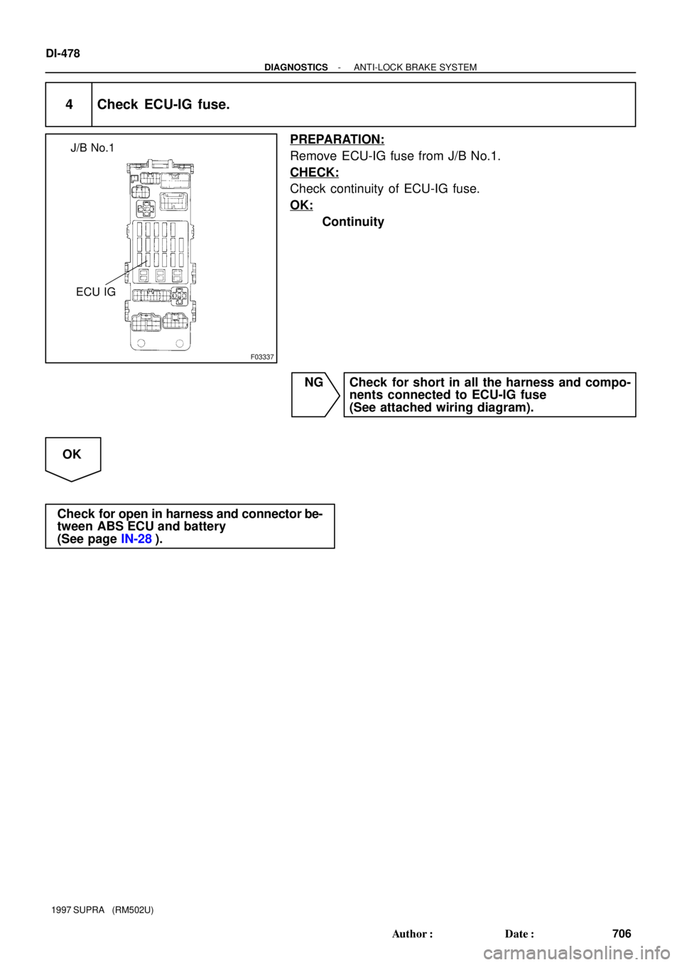
F03337
ECU IG J/B No.1
DI-478
- DIAGNOSTICSANTI-LOCK BRAKE SYSTEM
706 Author�: Date�:
1997 SUPRA (RM502U)
4 Check ECU-IG fuse.
PREPARATION:
Remove ECU-IG fuse from J/B No.1.
CHECK:
Check continuity of ECU-IG fuse.
OK:
Continuity
NG Check for short in all the harness and compo-
nents connected to ECU-IG fuse
(See attached wiring diagram).
OK
Check for open in harness and connector be-
tween ABS ECU and battery
(See page IN-28).
Page 770 of 1807

DTC 43, 45 Malfunction is Deceleration Sensor
(SPORT ABS (2JZ-GTE Engine) only)
CIRCUIT DESCRIPTION
DTC No.DTC Dete")
- DIAGNOSTICSANTI-LOCK BRAKE SYSTEM
DI-479
707 Author�: Date�:
1997 SUPRA (RM502U)
DTC 43, 45 Malfunction is Deceleration Sensor
(SPORT ABS (2JZ-GTE Engine) only)
CIRCUIT DESCRIPTION
DTC No.DTC Detecting ConditionTrouble Area
43
Either of the following (1) or (2) is detected:
(1) Input from the deceleration sensor does not change at one
cycle (0 km/h " more than 30km/h " 0 km/h) for 16 times
continuously.
(2) When the brake pedal is not depressed at vehicle speed of
5 km/h or more, forward and backward G (more than 0.4 G) is
detected for 30 seconds or more.
�Deceleration sensor
�Wire harness for deceleration sensor system
45
At vehicle speed of 30 km/h or more, the deceleration sensor
output and vehicle acceleration from wheel speed remain ab-
normally different for 60 seconds or more.�Deceleration sensor
�Wire harness for deceleration sensor system
INSPECTION PROCEDURE
1 Check deceleration sensor (See page DI-442).
NG Replace deceleration sensor.
OK
2 Check for open or short in harness and connector between sensor and ABS ECU
(See page IN-28).
NG Repair or replace harness and connector.
OK
Check and replace ABS ECU.
DI4VG-01
Page 771 of 1807
F03338
Deceleration sensor
3
5
1
2
A23
A23
A23
A23B
W-B
W
R
G
W-B
IG IEA20
A20
A20
A20
3
16
4
17VGS
GL2
GL1
GGNDABS ECU DI-480
- DIAGNOSTICSANTI-LOCK BRAKE SYSTEM
708 Author�: Date�:
1997 SUPRA (RM502U)
DTC 44 Deceleration Sensor Circuit
(SPORT ABS (2JZ-GTE Engine) only)
CIRCUIT DESCRIPTION
This sensor detects deceleration on the vehicle. The sensor signal is used in ABS control. If the sensor func-
tions abnormally, the ABS warning light comes on but the ABS still operates.
DTC No.DTC Detecting ConditionTrouble Area
44
Either of the following (1), (2) or (3) is detected:
(1) IG switch ON and output voltage of GL1 or GL2 remains
0.5 V or less or 4.5 V or more for more than 1.2 sec.
(2) At vehicle speed of 0 km/h, outputs of GL1 and GL2 re-
mains abnormally different for 60 sec. or more
(3) IG switch ON and VGS � 4.4 V, VGS � 5.5 V continues
for 1.2 sec. or more.
�Deceleration sensor
�Open or short in deceleration sensor circuit
WIRING DIAGRAM
DI4VH-01
Page 772 of 1807
F02629F03339F03340
ON
GL1VGS
GL2 (+)
(-)
- DIAGNOSTICSANTI-LOCK BRAKE SYSTEM
DI-481
709 Author�: Date�:
1997 SUPRA (RM502U)
INSPECTION PROCEDURE
1 Check for open and short in harness and connector between sensor and ABS
ECU (See page IN-28).
NG Repair or replace harness or connector.
OK
2 Check voltage between terminals GL1, GL2, VGS of ECU and body ground.
PREPARATION:
(a) Remove ABS ECU with connectors still connected.
(b) Disconnect sensor connector.
(c) Turn the ignition switch ON.
CHECK:
Measure voltage between terminals GL1, GL2, VGS of ECU
and body ground.
OK:
Voltage:
GL1, GL2: 0.5 - 4.5 V
VGS: 4.5 - 5.5 V
NG Check and replace ABS ECU.
OK
Check and replace deceleration sensor.
Page 773 of 1807
F03341
R/B No.2J/B No.1Stop Light
SwitchABS ECU
125
Light
Failure
Sensor
Stop LightJ/B
No.11
10IH
IC
A18 A22 *1*2
G-WG-W
G-W1
2 W STOP
210
1B 1I W-LPOWER
22 W
2
2A
ALTR/B No.2
B
Battery
NORMAL ABS (2JZ-GE Engine)
SPORT ABS (2JS-GTE Engine)
*1:
*2:
1
DI-482
- DIAGNOSTICSANTI-LOCK BRAKE SYSTEM
710 Author�: Date�:
1997 SUPRA (RM502U)
DTC 49 Stop Light Switch Circuit
CIRCUIT DESCRIPTION
This stop light switch senses whether the brake pedal is depressed or released, and sends a signal to the
ECU.
DTC No.DTC Detecting ConditionTrouble Area
491.2 - 1.7 V of STP voltage is continued for 0.3 sec. or more.�Open in stop light circuit
WIRING DIAGRAM
INSPECTION PROCEDURE
1 Check operation of stop light.
CHECK:
Check that stop light lights up when brake pedal is depressed and turns off when brake pedal is released.
NG Replace stop light bulb.
OK
DI4VI-01
Page 774 of 1807
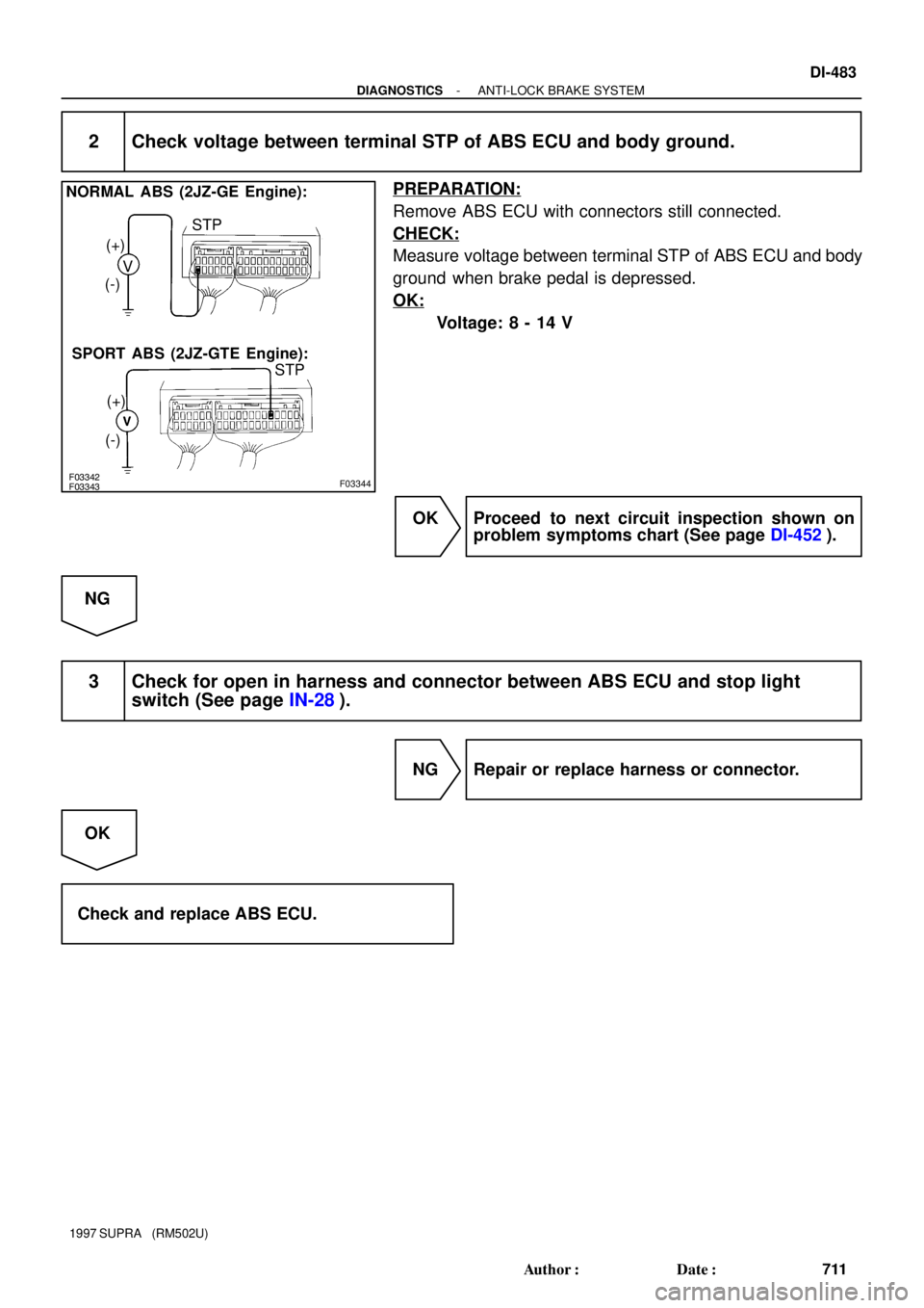
F03342F03343F03344
NORMAL ABS (2JZ-GE Engine):
SPORT ABS (2JZ-GTE Engine):V (+)
(-)
(+)
(-)STP
STP
- DIAGNOSTICSANTI-LOCK BRAKE SYSTEM
DI-483
711 Author�: Date�:
1997 SUPRA (RM502U)
2 Check voltage between terminal STP of ABS ECU and body ground.
PREPARATION:
Remove ABS ECU with connectors still connected.
CHECK:
Measure voltage between terminal STP of ABS ECU and body
ground when brake pedal is depressed.
OK:
Voltage: 8 - 14 V
OK Proceed to next circuit inspection shown on
problem symptoms chart (See page DI-452).
NG
3 Check for open in harness and connector between ABS ECU and stop light
switch (See page IN-28).
NG Repair or replace harness or connector.
OK
Check and replace ABS ECU.