Page 783 of 1807
F02629F03357F03358
LOCK
OpenContinuity
(-) (+)
F02629F03359F03360
LOCK
(-)
(+)
64 1 2
DI-492
- DIAGNOSTICSANTI-LOCK BRAKE SYSTEM
720 Author�: Date�:
1997 SUPRA (RM502U)
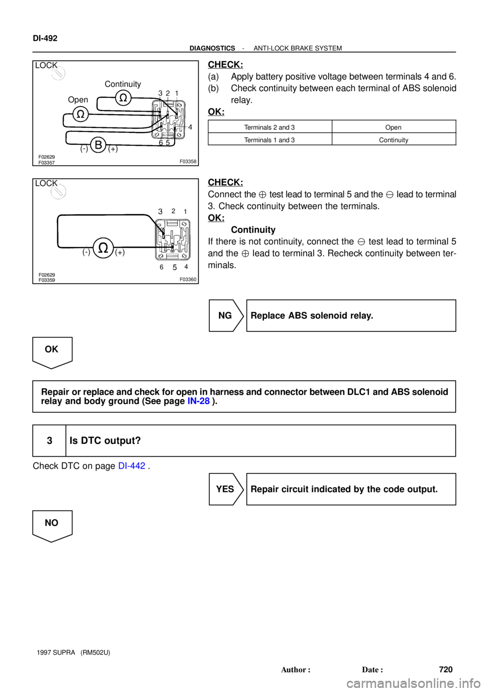
CHECK:
(a) Apply battery positive voltage between terminals 4 and 6.
(b) Check continuity between each terminal of ABS solenoid
relay.
OK:
Terminals 2 and 3Open
Terminals 1 and 3Continuity
CHECK:
Connect the � test lead to terminal 5 and the � lead to terminal
3. Check continuity between the terminals.
OK:
Continuity
If there is not continuity, connect the � test lead to terminal 5
and the � lead to terminal 3. Recheck continuity between ter-
minals.
NG Replace ABS solenoid relay.
OK
Repair or replace and check for open in harness and connector between DLC1 and ABS solenoid
relay and body ground (See page IN-28).
3 Is DTC output?
Check DTC on page DI-442.
YES Repair circuit indicated by the code output.
NO
Page 784 of 1807
- DIAGNOSTICSANTI-LOCK BRAKE SYSTEM
DI-493
721 Author�: Date�:
1997 SUPRA (RM502U)
4 Does ABS warning light go off if short pin is removed?
NO Check for short in harness and connector be-
tween warning light and DLC1 and ECU (See
page IN-28).
YES
5 Check ABS solenoid relay (See step No.2).
NG Replace ABS control relay.
OK
Repair or replace and check for short in harness and connector between DLC1 and ABS solenoid
relay (See page IN-28).
Page 785 of 1807
F03361
ABS ECU
12 V
Tc
A20 A1998
*1 *2
R
R
R
IF1
11
P-B
II1 DLC1
R
*121*2P-B R
*1
*2
DLC2
11 Tc E
13
BR
BR BR
ED
IJ1 18BR
Tc E
134
NORMAL ABS (2JZ-GE Engine)
SPORT ABS (2JZ-GTE Engine)
*1:
*2:
S-17-1 Iei-23-1-A
F00041
DLC2
DLC1
E1Tc
E1
Tc
DI-494
- DIAGNOSTICSANTI-LOCK BRAKE SYSTEM
722 Author�: Date�:
1997 SUPRA (RM502U)
Tc Terminal Circuit
CIRCUIT DESCRIPTION
Connecting terminals Tc and E1 of the DLC1 or the DLC1 or the DLC2 causes the ECU to display the DTC
by flashing the ABS warning light.
WIRING DIAGRAM
INSPECTION PROCEDURE
1 Check voltage between terminals Tc and E1 of DLC2 or DLC1.
PREPARATION:
Turn ignition switch ON.
CHECK:
Measure voltage between terminals Tc and E1 of DLC2 or
DLC1.
OK:
Voltage: 10 - 14 V
OK If ABS warning light does not blink even after Tc
and E1 are connected, the ECU may be defec-
tive.
NG
DI4VM-01
Page 786 of 1807
- DIAGNOSTICSANTI-LOCK BRAKE SYSTEM
DI-495
723 Author�: Date�:
1997 SUPRA (RM502U)
2 Check for open and short in harness and connector between ABS ECU and
DLC2 or DLC1, DLC2 or DLC1 and body ground (See page IN-28).
NG Repair or replace harness or connector.
OK
Check and replace ABS ECU.
Page 787 of 1807
F03362
ABS ECU
Ts 8
*1*2
IJ1 DLC1
21 15
BR
EDTc E13
16
NORMAL ABS (2JZ-GE Engine)
SPORT ABS (2JZ-GTE Engine)
*1:
*2:
YY12 VA18A20
F00007lei-23-1-A
E1
Ts
DLC1
DI-496
- DIAGNOSTICSANTI-LOCK BRAKE SYSTEM
724 Author�: Date�:
1997 SUPRA (RM502U)
Ts Terminal Circuit
CIRCUIT DESCRIPTION
The sensor check circuit detects abnormalities in the speed sensor signal which cannot be detected with
the DTC check.
Connecting terminals Ts and E1 of the DLC1 in the engine compartment starts the check.
WIRING DIAGRAM
INSPECTION PROCEDURE
1 Check voltage between terminals Ts and E1 of DLC1.
PREPARATION:
Turn ignition switch ON.
CHECK:
Measure voltage between terminals Ts and E1 of DLC1.
OK:
Voltage: 10 - 14 V
OK If ABS warning light does not blink even after Ts
and E1 are connected, the ECU may be defec-
tive.
NG
DI4VN-01
Page 788 of 1807
- DIAGNOSTICSANTI-LOCK BRAKE SYSTEM
DI-497
725 Author�: Date�:
1997 SUPRA (RM502U)
2 Check for open and short in harness and connector between ABS ECU and
DLC1, DLC1 and body ground (See page IN-28).
NG Repair or replace harness or connector.
OK
Check and replace ABS ECU.
Page 789 of 1807
F03363
DI-498
- DIAGNOSTICSANTI-LOCK BRAKE SYSTEM
726 Author�: Date�:
1997 SUPRA (RM502U)
Check for Fluid Leakage
Check for fluid leakage from actuators or hydraulic lines.
DI4VO-01
Page 829 of 1807

DTC 61, 62, 63, 64 Spee")
BR3583
BR3582F00010
Speed Sensor
High Speed Rotor
+V
-VLow SpeedTo ECU Magnet
CoilNS
DI-538
- DIAGNOSTICSABS & TRACTION CONTROL SYSTEM
766 Author�: Date�:
1997 SUPRA (RM502U)
DTC 61, 62, 63, 64 Speed Sensor Circuit
CIRCUIT DESCRIPTION
The speed sensor detects the wheel speed and sends the ap-
propriate signals to the ECU. These signals are used to control
both the ABS and TRAC control systems. The front and rear ro-
tors each have 48 serrations.
When the rotors rotate, the magnetic field emitted by the perma-
nent magnet in the speed sensor generates an AC voltage.
Since the frequency of this AC voltage changes in direct propor-
tion to the speed of the rotor, the frequency is used by the ECU
to detect the speed of each wheel.
DTC No.DTC Detecting ConditionTrouble Area
61,62,63,64
When the brake switch is OFF, one of the symmetrical wheels'
speed becomes one eight or less of the slowest speed of other
3 wheels continuously for 10 sec. or more.�Right front, left front, right rear and left rear speed sensor
�Wire harness and connector (FRO, FLO, RRO and RLO
circuit)
�Throttle control ECU
HINT:
DTC No.61 is for the right front speed sensor.
DTC No.62 is for the left front speed sensor.
DTC No.63 is for the right rear speed sensor.
DTC No.64 is for the left rear speed sensor.
DI4W6-01

SPORT ABS (2JZ-GTE Engine)
*1:
*2:
S-17-1")


SPORT ABS (2JZ-GTE Engine)
*1:
*2:
YY12 VA18A20
F00007lei-23-1-A
E1
Ts
DLC1
DI-496
- DIAGNOSTICSANTI-LOCK BRAKE SYSTEM")