Page 103 of 1807

22SUPRAÐOUTLINE OF NEW FEATURES
SUPRA
OUTLINE NEW FEATURES
The Supra, which represents Toyota's advanced automotive technology, has earned a reputation as a truly luxurious
sports car. The following changes have been made for the 1997 model year.
1. Model Line±Up
�The JZA80L±ALPVZA model has been discontinued.
�The JZA80L±ALFVZA and JZA80L±AJFVZA models have been added.
2. Exterior Design
�The multi±reflector type headlights are adopted.
�The design of the turn signal light, front bumper and rear combination light has been changed.
3. Interior Equipment
The front seats have been changed from the separate±headrest type seats of the '96 model to the integrated headrest
type seats without changing their basic design.
4. 2JZ±GTE Engine
An aluminum radiator core is adopted for weight reduction.
5. Differential
�A differential gear ratio has been changed on he 2JZ±GE engine model.
�A helical gear type torque±sensing LSD is available as an option on the 2JZ±GE engine model and 2JZ±GTE engine
with automatic transmission model.
6. Drive Shaft
An outboard joint of drive shaft has been changed from cross±groove type CVJ (Constant±Velocity Joint) to Rzeppa
type CVJ on the 2JZ±GE engine model.
7. Brakes
�A master cylinder diameter has been changed on the 2JZ±GTE engine model.
�An ABS has been changed to the 2±position solenoid valve type actuator.
Page 161 of 1807

INTERIOR LIGHT SYSTEM
SymptomSuspect AreaSee page
Only one light does not light up.1. Bulb
2. Wire Harness
Inter")
- BODY ELECTRICALBODY ELECTRICAL SYSTEM
BE-5
1983 Author�: Date�:
1997 SUPRA (RM502U)
INTERIOR LIGHT SYSTEM
SymptomSuspect AreaSee page
Only one light does not light up.1. Bulb
2. Wire Harness
Interior light does not light up (All).
1. DOME Fuse (R/B No.2)
2. Integration Relay
3. Wire Harness
BE-28
ºIlluminated Entry Systemº does not operate.
1. Integration Relay
2. Door Courtesy Switch
3. Door Key Lock and Unlock Switch
4. Door Unlock Detection Switch
5. Wire HarnessBE-28
BE-28
DI-656
DI-638
Front personal light does not light up.
1. Bulb
2. Front Personal Light
3. Wire Harness
BE-28
Luggage room light does not light up.1. Bulb
2. Luggage Room Light Switch
BE-28
BACK-UP LIGHT SYSTEM
SymptomSuspect AreaSee page
Back Up Light does not light up.
1. Bulb
2. GAUGE Fuse (J/B No.1)
3. Ignition Switch
4. Back-up Light Switch (M/T)
5. Park/Neutral Position Switch (A/T)
6. Wire Harness
BE-13
BE-31
DI-354
DI-423
Back Up Light remains always on.1. Wire Harness
Only one light does not light up.1. Bulb
2. Wire Harness
STOP LIGHT SYSTEM
SymptomSuspect AreaSee page
Stop light does not light up.
1. Bulb
2. STOP Fuse (J/B No.1)
3. Stop Light Switch
4. Wire Harness
BE-33
Stop light remains always on.1. Stop Light Switch
2. Wire HarnessBE-33
Only one light does not light up.1. Bulb
2. Wire Harness
Page 183 of 1807
Z18226
Personal LightDoor Key Lock and Unlock Switch
Door Lock Motor and Unlock Detection Switch
Luggage Room Light Switch
Luggage Room Light
Door Courtesy Switches Door Lock Motor and
Unlock Detection Switch �R/B No.2Integration
Relay
DOME Fuse
BE0DZ-01
- BODY ELECTRICALINTERIOR LIGHT SYSTEM
BE-27
2005 Author�: Date�:
1997 SUPRA (RM502U)
INTERIOR LIGHT SYSTEM
LOCATION
Page 184 of 1807

INSPECTION
1. INSPECT INTERIOR LIGHT CONTINUITY
Switch posit")
BE0E0-02
N08914
1
3
N08913
1
2
N08920
N08130
N08912
BE-28
- BODY ELECTRICALINTERIOR LIGHT SYSTEM
2006 Author�: Date�:
1997 SUPRA (RM502U)
INSPECTION
1. INSPECT INTERIOR LIGHT CONTINUITY
Switch positionTester connectionSpecified condition
DOOR1 - 3Continuity
OFF-No continuity
2. INSPECT PERSONAL LIGHT CONTINUITY
Switch positionTester connectionSpecified condition
OFF-No continuity
*ON1 - 2Continuity
* Set the interior light switch to OFF or DOOR.
If continuity is not as specified, replace the light assembly or
bulb.
3. INSPECT LUGGAGE ROOM LIGHT CONTINUITY
Switch positionTester connectionSpecified condition
OFF1 - 2No continuity
ON1 - 2Continuity
If continuity is not as specified, replace the light.
4. INSPECT DOOR COURTESY SWITCH CONTINUITY
Switch positionTester connectionSpecified condition
ON (SW pin released)1 - 2 - 3Continuity
OFF
(SW pin pushed in)-No continuity
If continuity is not as specified, replace the switch.
5. INSPECT LUGGAGE ROOM LIGHT SWITCH CONTI-
NUITY
ConditionTester connectionSpecified condition
ON (SW pin released)1 - Switch bodyContinuity
OFF
(SW pin pushed in)1 - Switch bodyNo continuity
If continuity is not as specified, replace the switch.
Page 185 of 1807
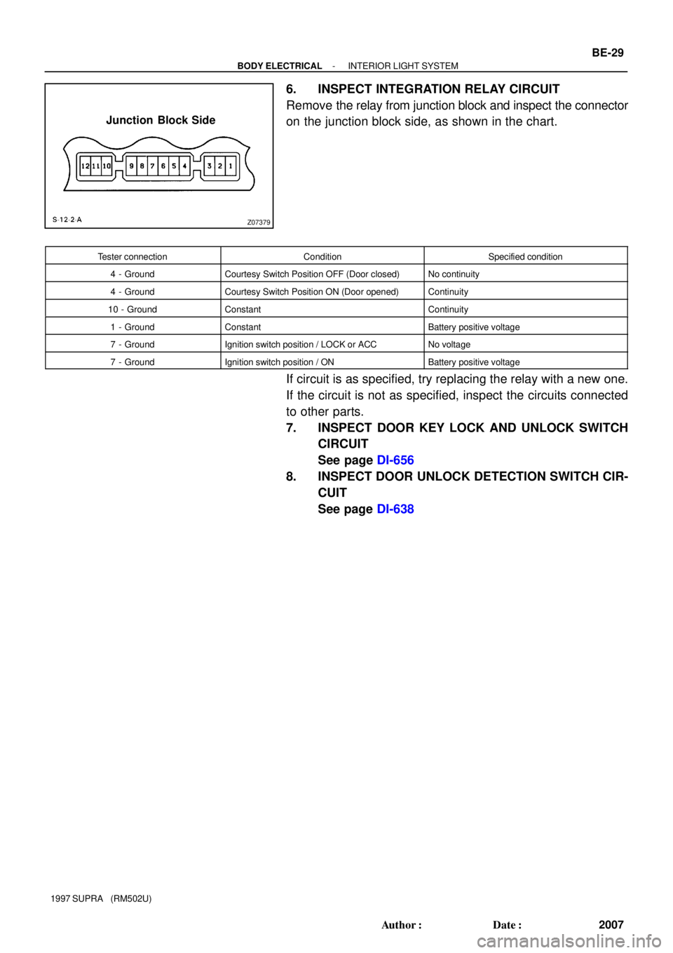
Z07379
Junction Block Side
- BODY ELECTRICALINTERIOR LIGHT SYSTEM
BE-29
2007 Author�: Date�:
1997 SUPRA (RM502U)
6. INSPECT INTEGRATION RELAY CIRCUIT
Remove the relay from junction block and inspect the connector
on the junction block side, as shown in the chart.
Tester connectionConditionSpecified condition
4 - GroundCourtesy Switch Position OFF (Door closed)No continuity
4 - GroundCourtesy Switch Position ON (Door opened)Continuity
10 - GroundConstantContinuity
1 - GroundConstantBattery positive voltage
7 - GroundIgnition switch position / LOCK or ACCNo voltage
7 - GroundIgnition switch position / ONBattery positive voltage
If circuit is as specified, try replacing the relay with a new one.
If the circuit is not as specified, inspect the circuits connected
to other parts.
7. INSPECT DOOR KEY LOCK AND UNLOCK SWITCH
CIRCUIT
See page DI-656
8. INSPECT DOOR UNLOCK DETECTION SWITCH CIR-
CUIT
See page DI-638
Page 283 of 1807
BO0QT-01
N16688
Roof Drip Side Finish Moulding
Roof Drip Side
Weatherstrip
Retainer
Roof Side Rail Weatherstrip
� Outside Garnish Seal � Outside Garnish Seal Normal Roof:
Sport Roof:
Holder RH
Sun Visor RHRemovable Roof
Front Roof Headlining
Holder LH
Interior Light
Sun Visor LH
Wind Deflector Panel
Front Pillar Garnish RH
Assist GripRemovable Roof Front
Weatherstrip
Front Pillar Garnish LH
� Outside Garnish Seal
Roof Drip Side
Finish Moulding
� Non-reusable part
- BODYROOF DRIP SIDE FINISH MOULDING
BO-27
2107 Author�: Date�:
1997 SUPRA (RM502U)
ROOF DRIP SIDE FINISH MOULDING
COMPONENTS
Page 284 of 1807

REMOVAL
1. Normal Roof:
REMOVE ROOF SIDE RAIL W")
BO0QU-01
N19390
: 5 Clips
Butyl Tape
N11770
Sport Roof:
Butyl Tape BO-28
- BODYROOF DRIP SIDE FINISH MOULDING
2108 Author�: Date�:
1997 SUPRA (RM502U)
REMOVAL
1. Normal Roof:
REMOVE ROOF SIDE RAIL WEATHERSTRIP
Using a clip remover, remove the 2 clips for front and 3 clips for
rear side of the weatherstrip and remove the weatherstrip.
2. Normal Roof:
REMOVE ROOF SIDE RAIL WEATHERSTRIP RETAIN-
ER
Remove the 3 screws and retainer.
3. Normal Roof:
REMOVE ROOF DRIP SIDE FINISH MOULDING
Remove the 9 screws and moulding.
4. Sports Roof:
REMOVE THESE PARTS:
(a) Removable roof
(b) Assist grip (See page BO-61)
HINT:
Tape a screwdriver tip before use.
(c) Front pillar garnishes (See page BO-61)
(d) Interior light
(e) Sun visors and holders
(f) Front roof headlining (See page BO-61)
(g) Wind deflector panel
5. Sports Roof:
REMOVE REMOVABLE ROOF FRONT WEATH-
ERSTRIP
(a) Remove the 2 nuts from the front weatherstrip.
(b) Using a clip remover, remove the 2 clips and weatherstrip.
6. Sports roof:
REMOVE ROOF DRIP SIDE FINISH MOULDING
Remove the 4 screws and moulding.
Page 288 of 1807

REMOVAL
1. REMOVE THESE PARTS:
(a) Inner rear view mirror
(b) Sun visors and holders
(c) Assist grip (Se")
BO0R0-01
N08453
BO5232
BO1689
BO-32
- BODYWINDSHIELD
2112 Author�: Date�:
1997 SUPRA (RM502U)
REMOVAL
1. REMOVE THESE PARTS:
(a) Inner rear view mirror
(b) Sun visors and holders
(c) Assist grip (See page BO-61)
HINT:
Tape a screwdriver tip before use.
(d) Front pillar garnishes (See page BO-61)
(e) Wiper arms and blades
(f) Cowl top ventilator louver
2. REMOVE WINDSHIELD MOULDING
(a) Using a knife, cut off the moulding as shown.
(b) Cut away the adhesive at the moulding installation area
as much as possible.
NOTICE:
Do not damage the body with the knife.
3. REMOVE WINDSHIELD GLASS
(a) Push piano wire through from the interior.
(b) Tie both wire ends to a wooden block or similar object.
HINT:
Apply adhesive tape to the outer surface of the glass to keep
the surface from being scratched.
NOTICE:
When separating the glass, take care not to damage the
paint and interior and exterior ornaments. To prevent
scratching the instrument panel when removing the wind-
shield, place a plastic sheet between the piano wire and
instrument panel.
(c) Cut the adhesive by pulling the piano wire around it.
(d) Remove the glass.
NOTICE:
Leave as much of the adhesive on the body as possible
when cutting off the glass.