Page 328 of 3342
D: ASSEMBLY
1. CRANKSHAFT AND PISTON
B2M0127A
Tightening torque: N⋅m (kg-m, ft-lb)
T: 44±2 (4.5±0.2, 32.5±1.4)
1) Install connecting rod bearings on connecting rods and
connecting rod caps.
CAUTION:
Apply oil to the surfaces of the connecting rod bear-
ings.
2) Install connecting rod on crankshaft.
CAUTION:
Position each connecting rod with the side marked
facing forward.
3) Install connecting rod cap with connecting rod nut.
Ensure the arrow on connecting rod cap faces the front
during installation.
CAUTION:
�Each connecting rod has its own mating cap. Make
sure that they are assembled correctly by checking
their matching number.
�When tightening the connecting rod nuts, apply oil
on the threads.
65
2-3SERVICE PROCEDURE
7. Cylinder Block
Page 341 of 3342

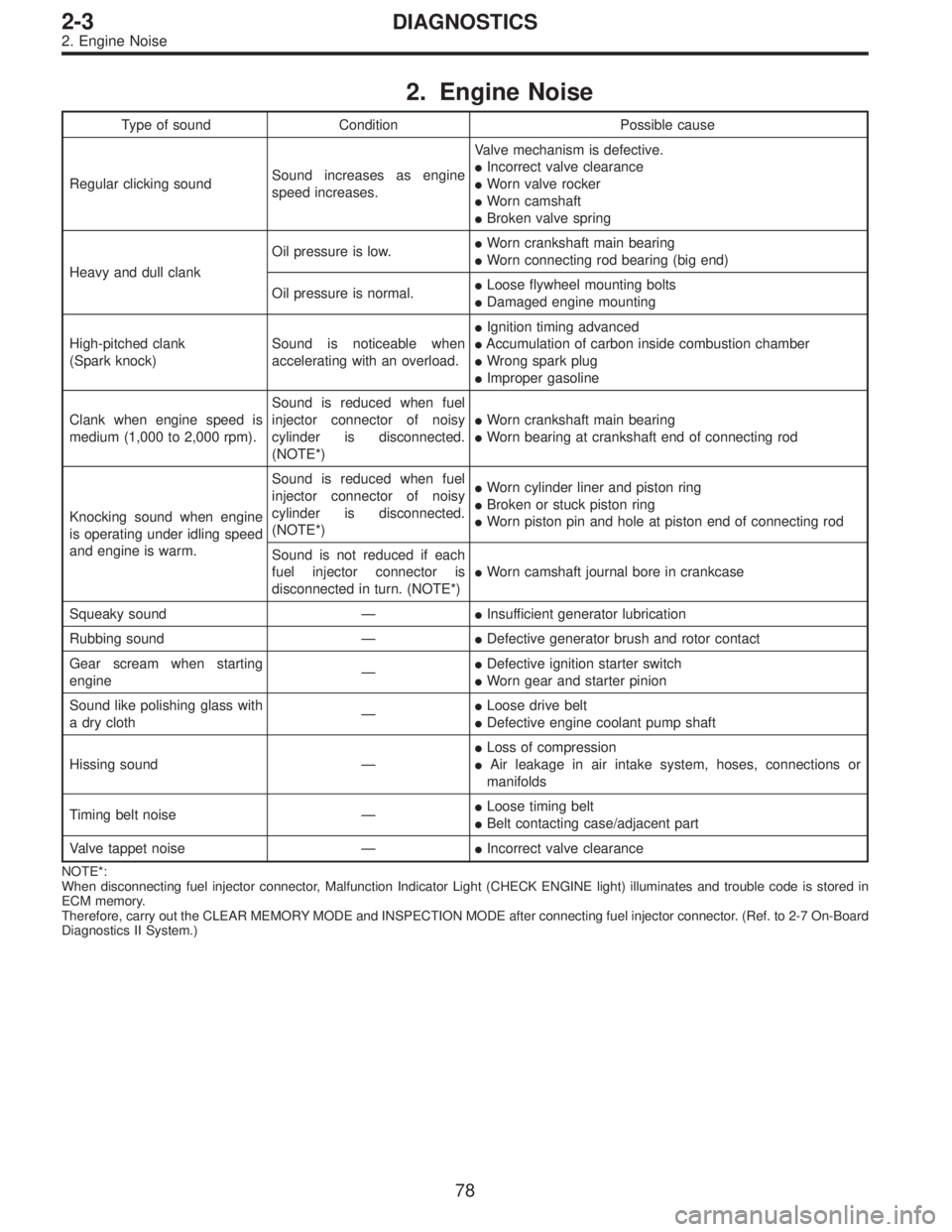
2. Engine Noise
Type of sound Condition Possible cause
Regular clicking soundSound increases as engine
speed increases.Valve mechanism is defective.
�Incorrect valve clearance
�Worn valve rocker
�Worn camshaft
�Broken valve spring
Heavy and dull clankOil pressure is low.�Worn crankshaft main bearing
�Worn connecting rod bearing (big end)
Oil pressure is normal.�Loose flywheel mounting bolts
�Damaged engine mounting
High-pitched clank
(Spark knock)Sound is noticeable when
accelerating with an overload.�Ignition timing advanced
�Accumulation of carbon inside combustion chamber
�Wrong spark plug
�Improper gasoline
Clank when engine speed is
medium (1,000 to 2,000 rpm).Sound is reduced when fuel
injector connector of noisy
cylinder is disconnected.
(NOTE*)�Worn crankshaft main bearing
�Worn bearing at crankshaft end of connecting rod
Knocking sound when engine
is operating under idling speed
and engine is warm.Sound is reduced when fuel
injector connector of noisy
cylinder is disconnected.
(NOTE*)�Worn cylinder liner and piston ring
�Broken or stuck piston ring
�Worn piston pin and hole at piston end of connecting rod
Sound is not reduced if each
fuel injector connector is
disconnected in turn. (NOTE*)�Worn camshaft journal bore in crankcase
Squeaky sound—�Insufficient generator lubrication
Rubbing sound—�Defective generator brush and rotor contact
Gear scream when starting
engine—�Defective ignition starter switch
�Worn gear and starter pinion
Sound like polishing glass with
a dry cloth—�Loose drive belt
�Defective engine coolant pump shaft
Hissing sound—�Loss of compression
�Air leakage in air intake system, hoses, connections or
manifolds
Timing belt noise—�Loose timing belt
�Belt contacting case/adjacent part
Valve tappet noise—�Incorrect valve clearance
NOTE*:
When disconnecting fuel injector connector, Malfunction Indicator Light (CHECK ENGINE light) illuminates and trouble code is stored in
ECM memory.
Therefore, carry out the CLEAR MEMORY MODE and INSPECTION MODE after connecting fuel injector connector. (Ref. to 2-7 On-Board
Diagnostics II System.)
78
2-3DIAGNOSTICS
2. Engine Noise
Page 352 of 3342
G2M0709
1. General Precautions
1) Before disassembling engine, place it on ST3.
ST1 498457000 ENGINE STAND ADAPTER RH
ST2 498457100 ENGINE STAND ADAPTER LH
ST3 499817000 ENGINE STAND
2) All parts should be thoroughly cleaned, paying special
attention to the engine oil passages, pistons and bearings.
3) Rotating parts and sliding parts such as piston, bearing
and gear should be coated with oil prior to assembly.
4) Be careful not to let oil, grease or coolant contact the
timing belt, clutch disc and flywheel.
5) All removed parts, if to be reused, should be reinstalled
in the original positions and directions.
6) Gaskets and lock washers must be replaced with new
ones. Liquid gasket should be used where specified to
prevent leakage.
7) Bolts, nuts and washers should be replaced with new
ones as required.
8) Even if necessary inspections have been made in
advance, proceed with assembly work while making
rechecks.
11
2-3bSERVICE PROCEDURE
1. General Precautions
Page 359 of 3342
B2M0737
7) Remove left-hand belt cover No. 2.
B2M0738
8) Remove right-hand belt cover No. 2.
B: INSPECTION
1. TIMING BELT
1) Check timing belt teeth for breaks, cracks, and wear. If
any fault is found, replace belt.
2) Check the condition of back side of belt; if any crack is
found, replace belt.
CAUTION:
�Be careful not to let oil, grease or coolant contact
the belt. Remove quickly and thoroughly if this hap-
pens.
G2M0115
�Do not bend the belt sharply.
Bending radius: h
60 mm (2.36 in) or more
18
2-3bSERVICE PROCEDURE
2. Timing Belt
Page 360 of 3342

2. BELT TENSION ADJUSTER
1) Visually check oil seals for leaks, and rod ends for
abnormal wear or scratches. If necessary, replace belt ten-
sion adjuster.
CAUTION:
Slight traces of oil at rod’s oil seal does not indicate a
problem.
2) While holding tensioner with both hands, push the rod
section against floor or wall ensuring the rod section will
react as follows:
(1) When applying a force of 147 N (15 kg, 33 lb), the
rod section should not sink.
(2) When applying a force of 147 to 490 N (15 to 50 kg,
33 to 110 lb), the rod section should maintain a projec-
tionally acting force and should not sink within 8.5 sec-
onds.
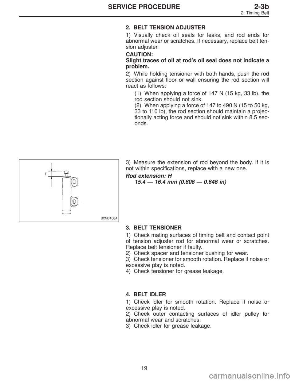
B2M0108A
3) Measure the extension of rod beyond the body. If it is
not within specifications, replace with a new one.
Rod extension: H
15.4 — 16.4 mm (0.606 — 0.646 in)
3. BELT TENSIONER
1) Check mating surfaces of timing belt and contact point
of tension adjuster rod for abnormal wear or scratches.
Replace belt tensioner if faulty.
2) Check spacer and tensioner bushing for wear.
3) Check tensioner for smooth rotation. Replace if noise or
excessive play is noted.
4) Check tensioner for grease leakage.
4. BELT IDLER
1) Check idler for smooth rotation. Replace if noise or
excessive play is noted.
2) Check outer contacting surfaces of idler pulley for
abnormal wear and scratches.
3) Check idler for grease leakage.
19
2-3bSERVICE PROCEDURE
2. Timing Belt
Page 372 of 3342

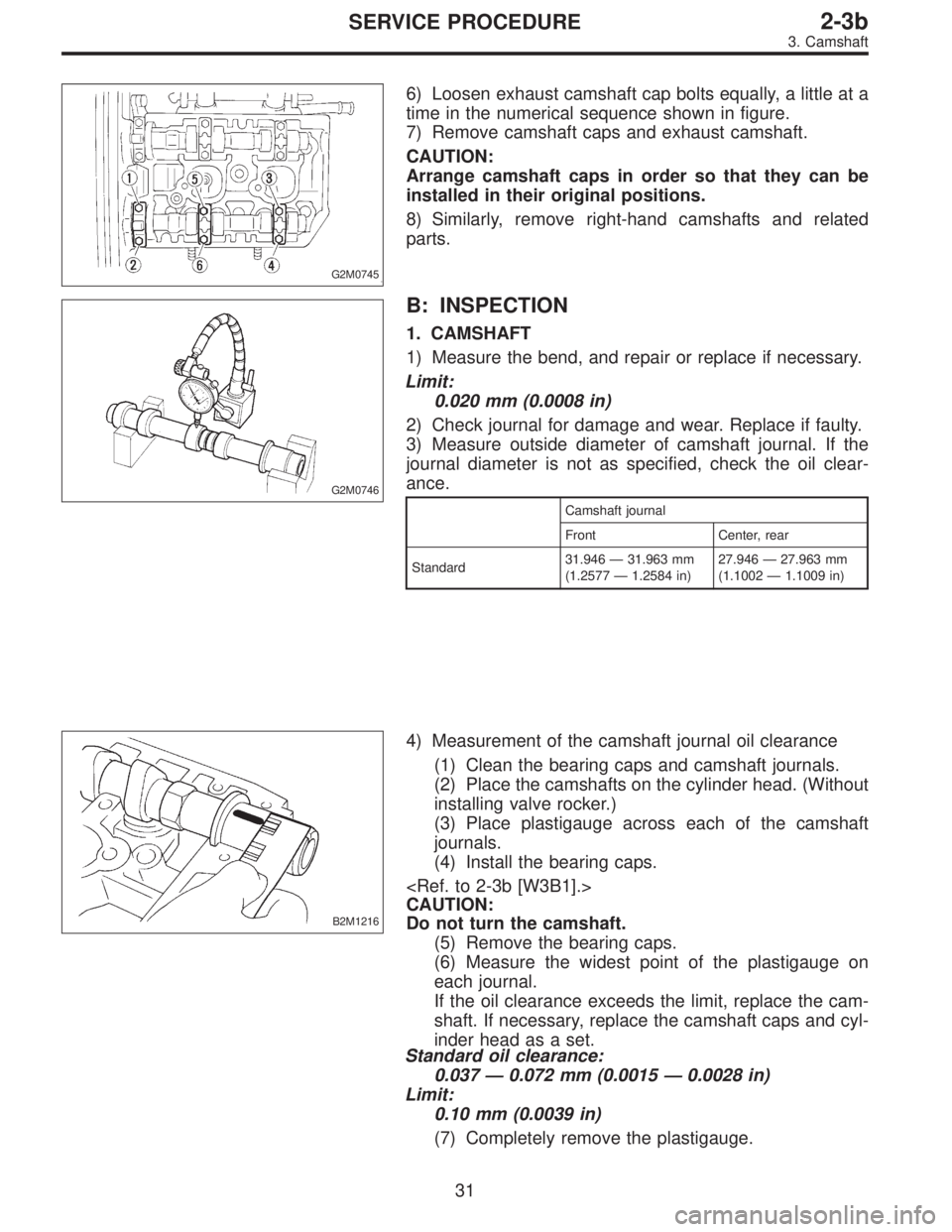
G2M0745
6) Loosen exhaust camshaft cap bolts equally, a little at a
time in the numerical sequence shown in figure.
7) Remove camshaft caps and exhaust camshaft.
CAUTION:
Arrange camshaft caps in order so that they can be
installed in their original positions.
8) Similarly, remove right-hand camshafts and related
parts.
G2M0746
B: INSPECTION
1. CAMSHAFT
1) Measure the bend, and repair or replace if necessary.
Limit:
0.020 mm (0.0008 in)
2) Check journal for damage and wear. Replace if faulty.
3) Measure outside diameter of camshaft journal. If the
journal diameter is not as specified, check the oil clear-
ance.
Camshaft journal
Front Center, rear
Standard31.946—31.963 mm
(1.2577—1.2584 in)27.946—27.963 mm
(1.1002—1.1009 in)
B2M1216
4) Measurement of the camshaft journal oil clearance
(1) Clean the bearing caps and camshaft journals.
(2) Place the camshafts on the cylinder head. (Without
installing valve rocker.)
(3) Place plastigauge across each of the camshaft
journals.
(4) Install the bearing caps.
CAUTION:
Do not turn the camshaft.
(5) Remove the bearing caps.
(6) Measure the widest point of the plastigauge on
each journal.
If the oil clearance exceeds the limit, replace the cam-
shaft. If necessary, replace the camshaft caps and cyl-
inder head as a set.
Standard oil clearance:
0.037—0.072 mm (0.0015—0.0028 in)
Limit:
0.10 mm (0.0039 in)
(7) Completely remove the plastigauge.
31
2-3bSERVICE PROCEDURE
3. Camshaft
Page 373 of 3342
B2M1209A
5) Check cam face condition; remove minor faults by
grinding with oil stone. Measure the cam height H; replace
if the limit has been exceeded.
Cam height: H
Standard:
Intake:
42.20—42.30 mm (1.6614—1.6654 in)
Exhaust:
Front: 42.50—42.60 mm (1.6732—1.6772 in)
Rear: 41.40—41.50 mm (1.6299—1.6339 in)
Limit:
Intake:
42.04 mm (1.6551 in)
Exhaust:
Front: 42.34 mm (1.6669 in)
Rear: 41.24 mm (1.6236 in)
Cam base circle diameter A:
28.0 mm (1.102 in)
B2M1217
6) Measure the thrust clearance of camshaft with dial
gauge. If the clearance exceeds the limit, replace caps and
cylinder head as a set. If necessary replace camshaft.
Standard:
0.040—0.080 mm (0.0016—0.0031 in)
Limit:
0.1 mm (0.004 in)
32
2-3bSERVICE PROCEDURE
3. Camshaft
Page 379 of 3342

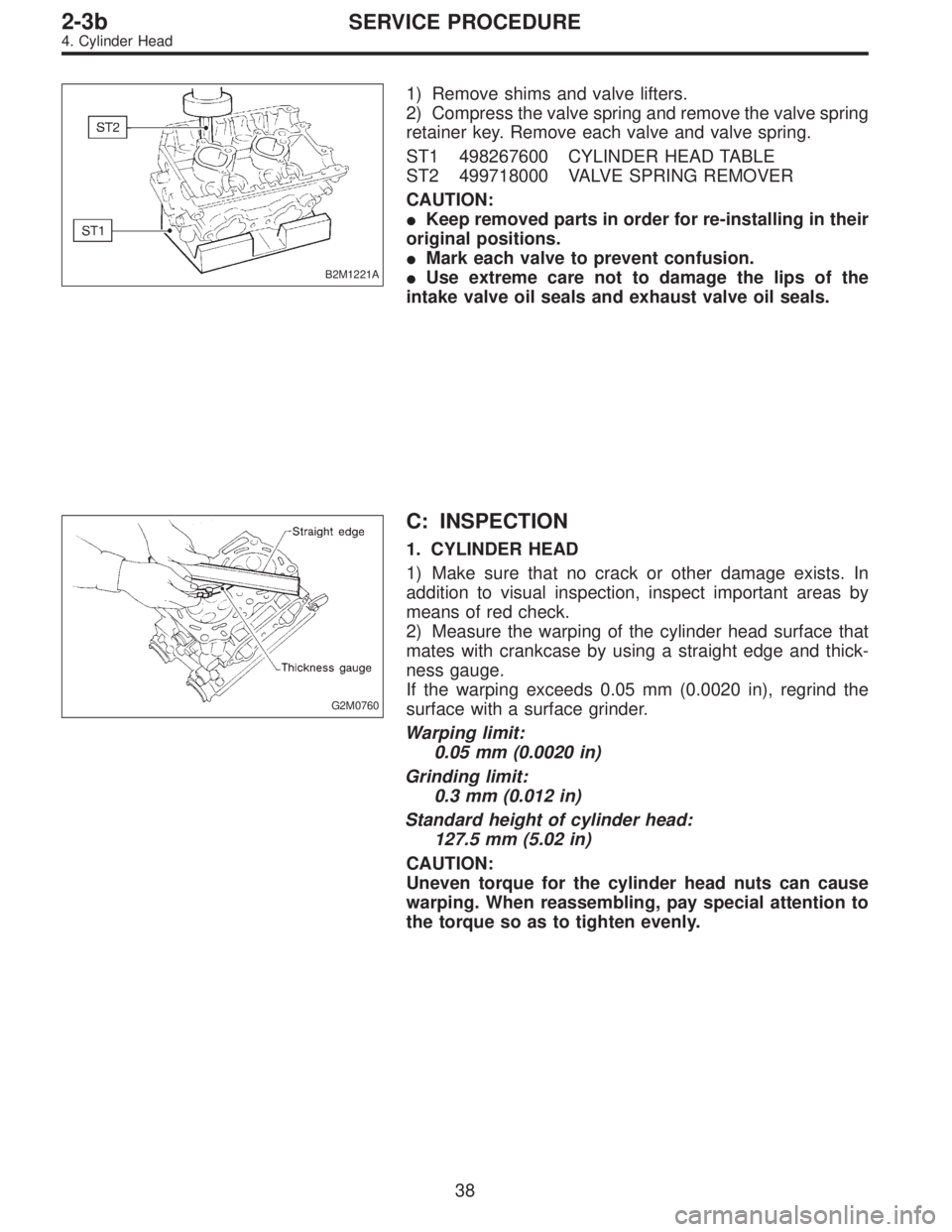
B2M1221A
1) Remove shims and valve lifters.
2) Compress the valve spring and remove the valve spring
retainer key. Remove each valve and valve spring.
ST1 498267600 CYLINDER HEAD TABLE
ST2 499718000 VALVE SPRING REMOVER
CAUTION:
�Keep removed parts in order for re-installing in their
original positions.
�Mark each valve to prevent confusion.
�Use extreme care not to damage the lips of the
intake valve oil seals and exhaust valve oil seals.
G2M0760
C: INSPECTION
1. CYLINDER HEAD
1) Make sure that no crack or other damage exists. In
addition to visual inspection, inspect important areas by
means of red check.
2) Measure the warping of the cylinder head surface that
mates with crankcase by using a straight edge and thick-
ness gauge.
If the warping exceeds 0.05 mm (0.0020 in), regrind the
surface with a surface grinder.
Warping limit:
0.05 mm (0.0020 in)
Grinding limit:
0.3 mm (0.012 in)
Standard height of cylinder head:
127.5 mm (5.02 in)
CAUTION:
Uneven torque for the cylinder head nuts can cause
warping. When reassembling, pay special attention to
the torque so as to tighten evenly.
38
2-3bSERVICE PROCEDURE
4. Cylinder Head