Page 427 of 3342
B2M0318
3. SIDE CLEARANCE
Measure clearance between oil pump inner rotor and pump
cover. If the clearance exceeds the limit, replace rotor or
pump body.
Side clearance:
Standard
0.02—0.07 mm (0.0008—0.0028 in)
Limit
0.15 mm (0.0059 in)
4. OIL RELIEF VALVE
Check the valve for fitting condition and damage, and the
relief valve spring for damage and deterioration. Replace
the parts if defective.
Relief valve spring:
Free length; 71.8 mm (2.827 in)
Installed length; 54.7 mm (2.154 in)
Load when installed; 77.08 N (7.86 kg, 17.33 lb)
5. OIL PUMP CASE
Check the oil pump case for worn shaft hole, clogged oil
passage, worn rotor chamber, cracks, and other faults.
6. OIL SEAL
Check the oil seal lips for deformation, hardening, wear,
etc. and replace if defective.
G2M0076
D: ASSEMBLY
1) Install front oil seal by using ST.
ST 499587100 OIL SEAL INSTALLER
CAUTION:
Use a new oil seal.
7
2-4SERVICE PROCEDURE
1. Oil Pump
Page 431 of 3342
G2M0082
15) Separate oil strainer from oil strainer stay.
G2M0376
16) Remove oil strainer.
G2M0377
17) Remove baffle plate and oil strainer stay.
B: INSPECTION
By visual check make sure oil pan, oil strainer, oil strainer
stay and baffle plate are not damaged.
G2M0377
C: INSTALLATION
CAUTION:
Before installing oil pan, clean sealant from oil and
engine block.
1) Install baffle plate and oil strainer stay.
Tightening torque:
5N⋅m (0.5 kg-m, 3.6 ft-lb)
11
2-4SERVICE PROCEDURE
2. Oil Pan and Oil Strainer
Page 438 of 3342
 O")
1. Engine Lubrication System
Before troubleshooting, make sure that the engine oil level
is correct and no oil leakage exists.
Trouble Possible cause Corrective action
1. Warning light remains
on.1) Oil pressure switch
failureCracked diaphragm or oil leakage within switch Replace.
Broken spring or seized contacts Replace.
2) Low oil pressureClogged oil filter Replace.
Malfunction of oil by-pass valve of oil filter Clean or replace.
Malfunction of oil relief valve of oil pump Clean or replace.
Clogged oil passage Clean.
Excessive tip clearance and side clearance of oil
pump rotor and gearReplace.
Clogged oil strainer or broken pipe Clean or replace.
3) No oil pressureInsufficient engine oil Replenish.
Broken pipe of oil strainer Replace.
Stuck oil pump rotor Replace.
2. Warning light does not
go on.1) Burn-out bulb Replace.
2) Poor contact of switch contact points Replace.
3) Disconnection of wiring Repair.
3. Warning light flickers
momentarily.1) Poor contact at terminals Repair.
2) Defective wiring harness Repair.
3) Low oil pressureCheck for the same pos-
sible causes as listed in
1.—2)
17
2-4DIAGNOSTICS
1. Engine Lubrication System
Page 577 of 3342
B2M0329A
2) Hardened facing
Correct by using emery paper or replace.
3) Oil soakage on facing
Replace clutch disc and inspect transmission front oil seal,
transmission case mating surface, engine rear oil seal and
other points for oil leakage.
B2M0330A
4) Deflection on facing
If deflection exceeds the specified value at the outer cir-
cumference of facing, repair or replace.
Limit for deflection:
1.0 mm (0.039 in) at R = 107 mm (4.21 in)
B2M0333A
5) Worn spline, loose rivets and torsion spring failure
Replace defective parts.
G2M0248
2. CLUTCH COVER
Visually check for the following items without
disassembling, and replace or repair if defective.
1) Loose thrust rivet.
2) Damaged or worn bearing contact area at center of
diaphragm spring.
G2M0249
3) Damaged or worn disc contact surface of pressure
plate.
4) Loose strap plate setting bolt.
5) Worn diaphragm sliding surface.
13
2-10SERVICE PROCEDURE
4. Clutch Disc and Cover
Page 608 of 3342

B: INSTALLATION
1. Install engine to transmission.
2. Tighten bolts which hold upper side of transmission to engine.
3. Remove lifting device and wire rope.
4. Remove garage jack.
5. Install pitching stopper.
AT model
6. Install torque converter onto drive plate.
7. Install canister and bracket.
8. Install power steering pump on bracket.
9. Tighten nuts which hold lower side of transmission to engine.
10. Tighten nuts which install front cushion rubber onto cross-
member.
11. Install front exhaust pipe and center exhaust pipe.
12. Connect hoses, connectors and cables.
13. Install air intake system.
�Air intake duct
�Air cleaner element and upper cover.
With A/C
14. Install A/C pressure hoses.
15. Install cooling system.
16. Install battery onto the vehicle, and connect cables.
17. Fill coolant.
18. Check ATF level, and connect if necessary. [AT]
19. Correct power steering oil, and bleed air.
20. Remove front hood stay, and close front hood.
21. Take off the vehicle from lift arms.
�
�
�
�
�
�
�
�
�
�
�
�
20
2-11SERVICE PROCEDURE
2. Engine
Page 638 of 3342
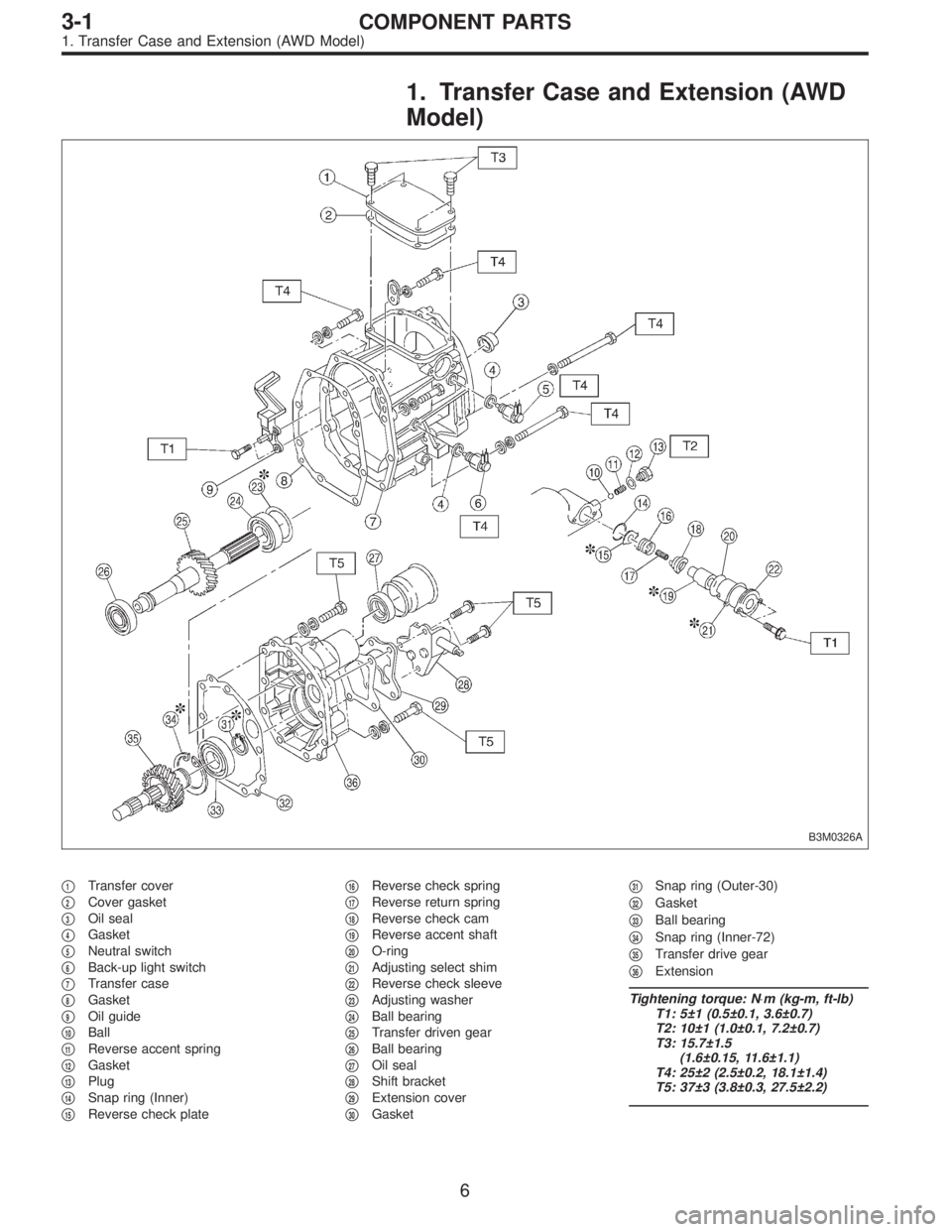
1. Transfer Case and Extension (AWD
Model)
B3M0326A
�1Transfer cover
�
2Cover gasket
�
3Oil seal
�
4Gasket
�
5Neutral switch
�
6Back-up light switch
�
7Transfer case
�
8Gasket
�
9Oil guide
�
10Ball
�
11Reverse accent spring
�
12Gasket
�
13Plug
�
14Snap ring (Inner)
�
15Reverse check plate�
16Reverse check spring
�
17Reverse return spring
�
18Reverse check cam
�
19Reverse accent shaft
�
20O-ring
�
21Adjusting select shim
�
22Reverse check sleeve
�
23Adjusting washer
�
24Ball bearing
�
25Transfer driven gear
�
26Ball bearing
�
27Oil seal
�
28Shift bracket
�
29Extension cover
�
30Gasket�
31Snap ring (Outer-30)
�
32Gasket
�
33Ball bearing
�
34Snap ring (Inner-72)
�
35Transfer drive gear
�
36Extension
Tightening torque: N⋅m (kg-m, ft-lb)
T1: 5±1 (0.5±0.1, 3.6±0.7)
T2: 10±1 (1.0±0.1, 7.2±0.7)
T3: 15.7±1.5
(1.6±0.15, 11.6±1.1)
T4: 25±2 (2.5±0.2, 18.1±1.4)
T5: 37±3 (3.8±0.3, 27.5±2.2)
6
3-1COMPONENT PARTS
1. Transfer Case and Extension (AWD Model)
Page 639 of 3342
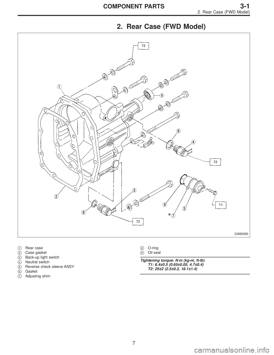
2. Rear Case (FWD Model)
G3M0265
�1Rear case
�
2Case gasket
�
3Back-up light switch
�
4Neutral switch
�
5Reverse check sleeve ASSY
�
6Gasket
�
7Adjusting shim�
8O-ring
�
9Oil seal
Tightening torque: N⋅m (kg-m, ft-lb)
T1: 6.4±0.5 (0.65±0.05, 4.7±0.4)
T2: 25±2 (2.5±0.2, 18.1±1.4)
7
3-1COMPONENT PARTS
2. Rear Case (FWD Model)
Page 648 of 3342
 The following job should be followed before disassem-
bly:
(1) Clean oil, grease, dirt and dust from transmission.
(2) Remove drain plug�
1to drain oil. After draining,
reti")
B3M0037A
B: PRECAUTIONS
1) The following job should be followed before disassem-
bly:
(1) Clean oil, grease, dirt and dust from transmission.
(2) Remove drain plug�
1to drain oil. After draining,
retighten it as before.
CAUTION:
Replace gasket with a new one.
Tightening torque:
44±3 N⋅m (4.5±0.3 kg-m, 32.5±2.2 ft-lb)
G3M0517
(3) Attach transmission to ST.
ST 499937100 TRANSMISSION STAND SET
2) Rotating parts should be coated with oil prior to assem-
bly.
3) All disassembled parts, if to be reused, should be rein-
stalled in the original positions and directions.
4) Gaskets and lock washers must be replaced with new
ones.
5) Liquid gasket should be used where specified to pre-
vent leakage.
6) Fill transmission gear oil through the oil level gauge
hole up to upper point level gauge.
C: INSPECTION
Disassembled parts should be washed clean first and then
inspected carefully.
1) Bearings
Replace bearings in the following cases:
�Bearings whose balls, outer races and inner races are
broken or rusty.
�Worn bearings
�Bearings that fail to turn smoothly or make abnormal
noise when turned after gear oil lubrication.
B3M0038A
The ball bearing�3on the rear side of the drive pinion shaft
�
2should be checked for smooth rotation before the drive
pinion assembly is disassembled. In this case, because a
preload is working on the bearing, its rotation feels like it is
slightly dragging unlike the other bearings.
�Bearings having other defects
16
3-1SERVICE PROCEDURE
1. General

 Separate oil strainer from oil strainer stay.
G2M0376
16) Remove oil strainer.
G2M0377
17) Remove baffle plate and oil strainer stay.
B: INSPECTION
By visual check make sure oil pan, oil s")
 Hardened facing
Correct by using emery paper or replace.
3) Oil soakage on facing
Replace clutch disc and inspect transmission front oil seal,
transmission case mating surface, engine rear")