Page 798 of 3342
G3M0454
2) Install the vane ring, rotor and vanes into the housing
in this sequence.
G3M0455
3) Install the return spring and retainer between the hous-
ing and cam ring.
G3M0456
4) Install the control piston to the oil pump housing.
NOTE:
Fit the seal in the piston groove, with the red seals facing
the top side. (Two side seals and one plain seal are
attached.)
5) Set the rotor at the center of the housing bore. Apply
ATF abundantly to each rotary portion.
G3M0446
6) Install the oil pump cover.
Tightening torque:
25±2 N⋅m (2.5±0.2 kg-m, 18.1±1.4 ft-lb)
NOTE:
�Align both pivots with the pivot holes of the cover, and
install the cover being careful not to apply undue force to
the pivots.
�After assembling, turn the oil pump shaft to check for
smooth rotation of the rotor.
G3M0449
NOTE:
�Install the oil seal retainer and seal rings (R) and (H)
after adjusting the drive pinion backlash and tooth contact.
92
3-2SERVICE PROCEDURE
7. Oil Pump Assembly
Page 803 of 3342

C: ASSEMBLY
G3M0909
�1Reverse clutch drum
�
2Lip seal
�
3Reverse clutch piston
�
4Lathe cut seal ring�
5Spring
�
6Spring retainer
�
7Snap ring�
8Dish plate
�
9Driven plate
�
10Drive plate�
11Retaining plate
�
12Snap ring
�
13High clutch drum
1) Using the ST1, ST2 and ST3 as those used in
disassembling, assemble piston�
3the springs�5, spring
retainer�
6and snap ring�7.
ST1 398673600 COMPRESSOR
ST2 398177700 INSTALLER
ST3 399893600 PLIERS
2) Assemble the dish plate�
8, driven plates�9, drive
plates�
10and retaining plate�11in that order and attach the
snap ring�
12.
NOTE:
Pay attention to the orientation of the dish plate.
3) Checking operation:
Apply compressed air intermittently to the oil hole, and
check the reverse clutch for smooth operation.
4) Measuring clearance (Retaining plate selection):
Standard value:
0.5—0.8 mm (0.020—0.031 in)
Allowable limit:
1.2 mm (0.047 in)
NOTE:
Before measuring clearance, place the same thickness of
shim on both sides to prevent retaining plate from tilting.
�Available retaining platesPart No. Thickness mm (in)
31567AA350
31567AA360
31567AA370
31567AA380
31567AA390
31567AA4004.6 (0.181)
4.8 (0.189)
5.0 (0.197)
5.2 (0.205)
5.4 (0.213)
5.6 (0.220)
97
3-2SERVICE PROCEDURE
9. Reverse Clutch
Page 805 of 3342
�
8Drive plate
�
9Driven plate (Thic")
C: ASSEMBLY
G3M0469
�1High clutch drum
�
2Lathe cut seal ring
�
3High clutch piston
�
4Lathe cut seal ring
�
5Spring retainer
�
6Snap ring
�
7Driven plate (Thinner)�
8Drive plate
�
9Driven plate (Thicker)
�
10Retaining plate
�
11Snap ring
�
12Thrust needle bearing
�
13High clutch hub
1) Using the ST1, ST2 and ST3 as those used in
disassembling, assemble the piston�
3, spring retainer�5,
and snap ring�
6.
ST1 398673600 COMPRESSOR
ST2 398177700 INSTALLER
ST3 399893600 PLIERS
2) Install the driven plate (thinner)�
7, drive plates�8,
driven plates (thicker)�
9, and retaining plate�10in that order.
Then attach the snap ring�
11.
3) Checking operation:
Apply compressed air intermittently to the oil hole, and
check the high clutch for smooth operation.
4) Measuring clearance (Retaining plate selection):
Standard value:
1.8—2.2 mm (0.071—0.087 in)
Allowable limit:
2.6 mm (0.102 in)
NOTE:
Before measuring clearance, place the same thickness of
shim on both sides to prevent retaining plate from tilting.
99
3-2SERVICE PROCEDURE
10. High Clutch
Page 827 of 3342
 Workshop
Provide a place that is clean and free from dust. Principally
the con")
G3M0854
1. Precaution
When disassembling or assembling the automatic
transmission, observe the following instructions.
1) Workshop
Provide a place that is clean and free from dust. Principally
the conventional workshop is suitable except for a dusty
place. In a workshop where grinding work, etc. which pro-
duces fine particles is done, make independent place
divided by the vinyl curtain or the equivalent.
2) Work table
The size of 1 x 1.5 m (40 x 60 in) is large enough to work,
and it is more desirable that its surface be covered with flat
plate like iron plate which is not rusted too much.
3) Cleaning of exterior
(1) Clean the exterior surface of transmission with
steam and/or kerosene prior to disassembly, however it
should be noted that vinyl tape be placed on the air
breather or oil level gauge to prevent infiltration of the
steam into the transmission and also the cleaning job
be done away from the place of disassembly and
assembly.
(2) Partial cleaning will do, depending on the extent of
disassembly (such as when disassembly is limited to
some certain parts).
4) Disassembly, assembly and cleaning
(1) Disassemble and assemble the transmission while
inspecting the parts in accordance with the Diagnostics.
(2) During job, don’t use gloves. Don’t clean the parts
with rags: Use chamois or nylon cloth.
(3) Pay special attention to the air to be used for clean-
ing. Get the moisture and the dust rid of the air as much
as possible. Be careful not to scratch or dent any part
while checking for proper operation with an air gun.
(4) Complete the job from cleaning to completion of
assembly as continuously and speedily as possible in
order to avoid occurrence of secondary troubles
caused by dust. When stopping the job unavoidably
cover the parts with clean chamois or nylon cloth to
keep them away from any dust.
(5) Use kerosene, white gasoline or the equivalent as
washing fluid. Use always new fluid for cleaning the
automatic transmission parts and never reuse. The
used fluid is usable in disassemble and assemble work
of engine and manual transmission.
(6) Although the cleaning should be done by dipping
into the washing fluid or blowing of the pressurized
washing fluid, the dipping is more desirable. (Do not rub
with a brush.) Assemble the parts immediately after the
cleaning without exposure to the air for a while. Besides
in case of washing rubber parts, perform the job quickly
not to dip them into the washing fluid for long time.
21
3-2SERVICE PROCEDURE
1. Precaution
Page 829 of 3342
 Raise ATF temperature to 60 to 80°C (140 to 176°F)
from 40 to 60°C (104 to 140°F) (when cold) by driving a
distance of 5 to 10 km (3 to 6 mi")
G3M0282
2. On-Car Service
A: INSPECTION
1. ATF LEVEL
1) Raise ATF temperature to 60 to 80°C (140 to 176°F)
from 40 to 60°C (104 to 140°F) (when cold) by driving a
distance of 5 to 10 km (3 to 6 miles).
NOTE:
The level of ATF varies with fluid temperature. Pay atten-
tion to the fluid temperature when checking oil level.
2) Make sure the vehicle is level. After selecting all posi-
tions (P, R, N, D, 3, 2, 1), set the selector leveler in“P”
range. Measure fluid level with the engine idling.
NOTE:
After running, idle the engine for one or two minutes before
measurement.
3) If the fluid level is below the center between upper and
lower marks, add the recommended ATF until the fluid level
is found within the specified range (above the center
between upper and lower marks). When the transmission
is hot, the level should be above the center of upper and
lower marks, and when it is cold, the level should be found
below the center of these two marks.
CAUTION:
�Use care not to exceed the upper limit level.
�ATF level varies with temperature. Remember that
the addition of fluid to the upper limit mark when the
transmission is cold will result in the overfilling of
fluid.
4) Fluid temperature rising speed
�By idling the engine
Time for temperature rise to 60°C (140°F) with atmo-
spheric temperature of 0°C (32°F): More than 25 minutes
Time for temperature rise to 30°C (86°F) with atmo-
spheric temperature of 0°C (32°F): Approx. 8 minutes
�By running the vehicle
Time for temperature rise to 60°C (140°F) with atmo-
spheric temperature of 0°C (32°F): More than 10 minutes
5) Method for checking fluid level upon delivery or at peri-
odic inspection
Check fluid level after a warm-up run of approx. 10 min-
utes. During the warm-up period, the automatic transmis-
sion functions can also be checked.
23
3-2SERVICE PROCEDURE
2. On-Car Service
Page 830 of 3342
 Ensure the vehicle is in safe condition.
NOTE:
Do not check the oil level nor add oil to the case with the
front end of the vehicle jacked-up; this will resul")
G3M0283
2. DIFFERENTIAL GEAR OIL LEVEL
1) Ensure the vehicle is in safe condition.
NOTE:
Do not check the oil level nor add oil to the case with the
front end of the vehicle jacked-up; this will result in an
incorrect reading of the oil level.
2) Check whether the oil level is between the upper (F)
and lower (L) marks. If it is below the lower limit mark, add
oil until the level reaches the upper mark.
G3M0854
3. OIL LEAKAGE
It is difficult to accurately determine the precise position of
a oil leak, since the surrounding area also becomes wet
with oil. The places where oil seals and gaskets are used
are as follows:
Jointing portion of the case
�Transmission case and oil pump housing jointing portion
�Torque converter clutch case and oil pump housing joint-
ing portion
�Transmission case and transmission cover jointing por-
tion (FWD)
�Transmission case and extension case jointing portion
(AWD)
G3M0855
Torque converter clutch case
�Engine crankshaft oil seal
�Torque converter clutch impeller sleeve oil seal
�ATF cooler pipe connector
�Torque converter clutch
�Torque converter clutch case
�Axle shaft oil seal
�O-ring on the outside diameter of axle shaft oil seal
holder
�O-ring on the differential oil gauge
�Differential oil drain plug
�Speedometer cable mounting portion
�Location of steel balls
24
3-2SERVICE PROCEDURE
2. On-Car Service
Page 831 of 3342
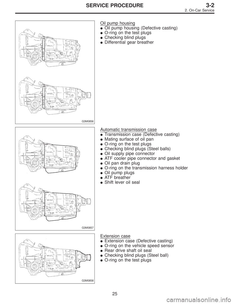
G3M0856
Oil pump housing
�Oil pump housing (Defective casting)
�O-ring on the test plugs
�Checking blind plugs
�Differential gear breather
G3M0857
Automatic transmission case
�Transmission case (Defective casting)
�Mating surface of oil pan
�O-ring on the test plugs
�Checking blind plugs (Steel balls)
�Oil supply pipe connector
�ATF cooler pipe connector and gasket
�Oil pan drain plug
�O-ring on the transmission harness holder
�Oil pump plugs
�ATF breather
�Shift lever oil seal
G3M0858
Extension case
�Extension case (Defective casting)
�O-ring on the vehicle speed sensor
�Rear drive shaft oil seal
�Checking blind plugs (Steel ball)
�O-ring on the test plugs
25
3-2SERVICE PROCEDURE
2. On-Car Service
Page 832 of 3342

The point listed above should be checked for fluid leak.
Checking method is as follows:
(1) Place the vehicle in the pit, and check w")
G3M0859
Transmission cover
�Transmission cover (Defective casting)
The point listed above should be checked for fluid leak.
Checking method is as follows:
(1) Place the vehicle in the pit, and check whether the
leaking oil is ATF or not. The ATF is wine red in color,
and can be discriminated easily from engine oil and
gear oil.
(2) Wipe clean the leaking oil and dust from a suspect-
able area, using a non-inflammable organic solvent
such as carbon tetrachloride.
(3) Run the engine to raise the fluid temperature, and
set the selector lever to“D”in order to increase the fluid
pressure and quickly detect a leaking point. Also check
for fluid leaks while shifting select lever to“R”,“2”, and
“1”.
G3M0289
B: ADJUSTMENT
1. BRAKE BAND
If the following abnormal shifting conditions are noted in a
road test, the brake band must be adjusted.
Improper brake band clearances and their symptoms
Clearance Problem
1. Too wide Upshift from 1st directly to 3rd gear occurs.
2. Wide�Engine rpm increases abruptly while upshifting from 1st
to 2nd gear or 3rd to 4th gear.
�Time lag of at least one second occurs during kickdown
operation from 3rd to 2nd gear.
3. Small“Braking”symptom occurs while upshifting from 2nd to 3rd
gear.
4. Too smallUpshifts from 2nd to 4th gear and downshifts from 4th to
2nd gear occur repeatedly.
26
3-2SERVICE PROCEDURE
2. On-Car Service
 Install the vane ring, rotor and vanes into the housing
in this sequence.
G3M0455
3) Install the return spring and retainer between the hous-
ing and cam ring.
G3M0456
4) Install the contro")