Page 930 of 3342
 Ensure the vehicle is in safe condition.
NOTE:
Do not check the oil level nor add oil to the case with the
front end of the vehicle jacked-up; this will resul")
G3M0283
2. DIFFERENTIAL GEAR OIL LEVEL
1) Ensure the vehicle is in safe condition.
NOTE:
Do not check the oil level nor add oil to the case with the
front end of the vehicle jacked-up; this will result in an
incorrect reading of the oil level.
2) Check whether the oil level is between the upper (F)
and lower (L) marks. If it is below the lower limit mark, add
oil until the level reaches the upper mark.
G3M0854
3. OIL LEAKAGE
It is difficult to accurately determine the precise position of
a oil leak, since the surrounding area also becomes wet
with oil. The places where oil seals and gaskets are used
are as follows:
Jointing portion of the case
�Transmission case and oil pump housing jointing portion
�Torque converter clutch case and oil pump housing joint-
ing portion
�Transmission case and transmission cover jointing por-
tion (FWD)
�Transmission case and extension case jointing portion
(AWD)
G3M0855
Torque converter clutch case
�Engine crankshaft oil seal
�Torque converter clutch impeller sleeve oil seal
�ATF cooler pipe connector
�Torque converter clutch
�Torque converter clutch case
�Axle shaft oil seal
�O-ring on the outside diameter of axle shaft oil seal
holder
�O-ring on the differential oil gauge
�Differential oil drain plug
�Speedometer cable mounting portion
�Location of steel balls
24
3-2SERVICE PROCEDURE
2. On-Car Service
Page 931 of 3342
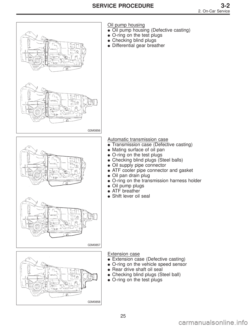
G3M0856
Oil pump housing
�Oil pump housing (Defective casting)
�O-ring on the test plugs
�Checking blind plugs
�Differential gear breather
G3M0857
Automatic transmission case
�Transmission case (Defective casting)
�Mating surface of oil pan
�O-ring on the test plugs
�Checking blind plugs (Steel balls)
�Oil supply pipe connector
�ATF cooler pipe connector and gasket
�Oil pan drain plug
�O-ring on the transmission harness holder
�Oil pump plugs
�ATF breather
�Shift lever oil seal
G3M0858
Extension case
�Extension case (Defective casting)
�O-ring on the vehicle speed sensor
�Rear drive shaft oil seal
�Checking blind plugs (Steel ball)
�O-ring on the test plugs
25
3-2SERVICE PROCEDURE
2. On-Car Service
Page 932 of 3342

The point listed above should be checked for fluid leak.
Checking method is as follows:
(1) Place the vehicle in the pit, and check w")
G3M0859
Transmission cover
�Transmission cover (Defective casting)
The point listed above should be checked for fluid leak.
Checking method is as follows:
(1) Place the vehicle in the pit, and check whether the
leaking oil is ATF or not. The ATF is wine red in color,
and can be discriminated easily from engine oil and
gear oil.
(2) Wipe clean the leaking oil and dust from a suspect-
able area, using a non-inflammable organic solvent
such as carbon tetrachloride.
(3) Run the engine to raise the fluid temperature, and
set the selector lever to“D”in order to increase the fluid
pressure and quickly detect a leaking point. Also check
for fluid leaks while shifting select lever to“R”,“2”, and
“1”.
G3M0289
B: ADJUSTMENT
1. BRAKE BAND
If the following abnormal shifting conditions are noted in a
road test, the brake band must be adjusted.
Improper brake band clearances and their symptoms
Clearance Problem
1. Too wide Upshift from 1st directly to 3rd gear occurs.
2. Wide�Engine rpm increases abruptly while upshifting from 1st
to 2nd gear or 3rd to 4th gear.
�Time lag of at least one second occurs during kickdown
operation from 3rd to 2nd gear.
3. Small“Braking”symptom occurs while upshifting from 2nd to 3rd
gear.
4. Too smallUpshifts from 2nd to 4th gear and downshifts from 4th to
2nd gear occur repeatedly.
26
3-2SERVICE PROCEDURE
2. On-Car Service
Page 939 of 3342
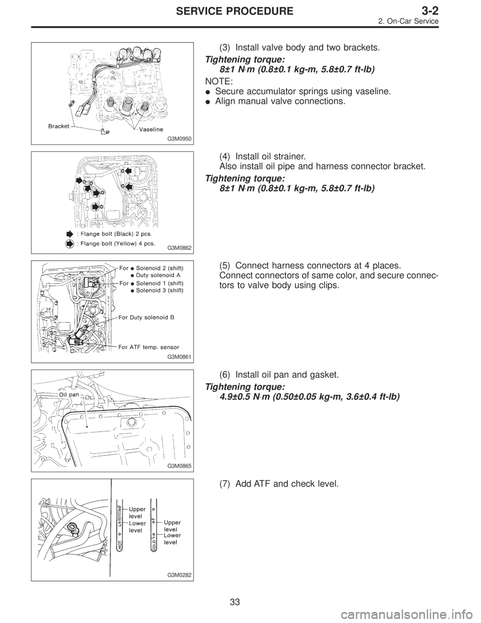
G3M0950
(3) Install valve body and two brackets.
Tightening torque:
8±1 N⋅m (0.8±0.1 kg-m, 5.8±0.7 ft-lb)
NOTE:
�Secure accumulator springs using vaseline.
�Align manual valve connections.
G3M0862
(4) Install oil strainer.
Also install oil pipe and harness connector bracket.
Tightening torque:
8±1 N⋅m (0.8±0.1 kg-m, 5.8±0.7 ft-lb)
G3M0861
(5) Connect harness connectors at 4 places.
Connect connectors of same color, and secure connec-
tors to valve body using clips.
G3M0865
(6) Install oil pan and gasket.
Tightening torque:
4.9±0.5 N⋅m (0.50±0.05 kg-m, 3.6±0.4 ft-lb)
G3M0282
(7) Add ATF and check level.
33
3-2SERVICE PROCEDURE
2. On-Car Service
Page 943 of 3342
G3M0782
(5) Install propeller shaft.
Tightening torque:
At rear differential
23±5 N⋅m (2.3±0.5 kg-m, 16.6±3.6 ft-lb)
At center bearing
39±5 N⋅m (4.0±0.5 kg-m, 28.9±3.6 ft-lb)
NOTE:
Align matching marks on propeller shaft and rear differen-
tial coupling.
G3M0305
(6) Install front exhaust pipe
Tightening torque:
At engine
29±5 N⋅m (3.0±0.5 kg-m, 21.7±3.6 ft-lb)
At hanger
29±5 N⋅m (3.0±0.5 kg-m, 21.7±3.6 ft-lb)
At front and rear connections
18±5 N⋅m (1.8±0.5 kg-m, 13.0±3.6 ft-lb)
G3M0313
(7) Lower and remove jack.
(8) Connect the following parts:
�Oxygen sensor connector
�Multi-connector
G3M0304
(9) Install pitching stopper.
Tightening torque:
Body side
57±10 N⋅m (5.8±1.0 kg-m, 42±7 ft-lb)
Engine side
49±5 N⋅m (5.0±0.5 kg-m, 36.2±3.6 ft-lb)
G3M0282
(10) Replenish ATF and check oil level. Check for
leaks.
37
3-2SERVICE PROCEDURE
2. On-Car Service
Page 944 of 3342

3. Performance Test
A: STALL TEST
1. GENERAL
The stall test is of extreme importance in diagnosing the
condition of the automatic transmission and the engine. It
should be conducted to measure the engine stall speeds in
all shift ranges except the P and N ranges.
Purposes of the stall test:
1) To check the operation of the automatic transmission
clutch.
2) To check the operation of the torque converter clutch.
3) To check engine performance.
2. TEST METHODS
Preparations before test:
�
1Check that throttle valve opens fully.
�
2Check that engine oil level is correct.
�
3Check that coolant level is correct.
�
4Check that ATF level is correct.
�
5Check that differential gear oil level is correct.
�
6Increase ATF temperature to 50 to 80°C (122 to 176°F)
by idling the engine for approximately 30 minutes (with
select lever set to“N”or“P”).
1) Install an engine tachometer at a location visible from
the driver’s compartment and mark the stall speed range
on the tachometer scale.
2) Place the wheel chocks at the front and rear of all
wheels and engage the parking brake.
3) Move the manual linkage to ensure it operates properly,
and shift the select lever to the 2 range.
B3M0286B
4) While forcibly depressing the foot brake pedal, gradu-
ally depress the accelerator pedal until the engine operates
at full throttle.
5) When the engine speed is stabilized, read that speed
quickly and release the accelerator pedal.
6) Shift the select lever to Neutral, and cool down the
engine by idling it for more than one minute.
7) Record the stall speed.
8) If stall speed in 2 range is higher than specifications,
forward clutch slipping on brake band slipping may occur.
To identify it, conduct the same test as above in D range.
9) Perform the stall tests with the select lever in the R
range.
CAUTION:
�Do not continue the stall test for MORE THAN FIVE
SECONDS at a time (from closed throttle, fully open
throttle to stall speed reading). Failure to follow this
instruction causes the engine oil and ATF to deterio-
rate and the clutch and brake band to be adversely
affected.
38
3-2SERVICE PROCEDURE
3. Performance Test
Page 947 of 3342

C: LINE PRESSURE TEST
1. GENERAL
If the clutch or the brake band shows a sign of slippage or
shifting sensation is not correct, the line pressure should be
checked.
�Excessive shocks during upshifting or shifting takes
place at a higher point than under normal circumstances,
may be due to the line pressure being too high.
�Slippage or inability to operate the vehicle may, in most
cases, be due to loss of oil pressure for the operation of
the clutch, brake band or control valve.
G3M0869
1) Line pressure measurement (under no load)
CAUTION:
�Before measuring line pressure, jack-up front
wheels (front-wheel-drive model) or all wheels (4-wheel
drive model).
�Maintain temperature of ATF at approximately 50°C
(122°F) during measurement.
(ATF will reach the above temperature after idling the
engine for approximately 30 minutes with select lever
in“N”or“P”.)
G3M0869
2) Line pressure measurement (under heavy load)
CAUTION:
�Before measuring line pressure, apply both foot and
parking brakes with all wheels chocked (Same as for
“stall”test conditions).
�Measure line pressure when select lever is in“R”,
“2”with engine under stall conditions.
�Measure line pressure within 5 seconds after shift-
ing the select lever to each position. (If line pressure
needs to be measured again, allow the engine to idle
and then stop. Wait for at least one minute before mea-
surement.)
�Maintain the temperature of ATF at approximately
50°C (122°F) during measurement. (ATF will reach the
above temperature after idling the engine for approxi-
mately 30 minutes with the select lever in“N”or“P”.)
41
3-2SERVICE PROCEDURE
3. Performance Test
Page 948 of 3342
 Temporarily attach the ST to a suitable place in the
driver’s compartment, remove the blind plug located in
front of the toe board and pass the hose of the ST to the
engin")
G3M0317
2. TEST METHODS
1) Temporarily attach the ST to a suitable place in the
driver’s compartment, remove the blind plug located in
front of the toe board and pass the hose of the ST to the
engine compartment.
ST 498575400 OIL PRESSURE GAUGE ASSY
�
1Pressure gauge hose
�
2Hole in toe board (blank cap hole)
�
3Brake pedal
G3M0869
2) Remove the test plug and install ST1 instead.
3) Connect ST1 with ST2.
ST1 498897200 OIL PRESSURE GAUGE ADAPTER
ST2 498575400 OIL PRESSURE GAUGE ASSY
4) Check for duty ratio changes by opening and closing
throttle valve using select monitor.
5) Check line pressure in accordance with the following
chart.
3. EVALUATION
NOTE:
�Under no load:“D”
�Under full load:“R”,“2”
(With engine running at stall speed)
Unit: kPa (kg/cm2, psi)
Line pressure
Duty ratio (%)“2”range“R”range“D”range
2200 cc 2500 cc
51,147—1,344
(11.7—13.1, 166—195)1,275—1,569
(13.0—16.0, 185—228)—
22——765—902
(7.8—9.2, 111—131)
100——235—481
(2.4—4.9, 34—70)392—490
(4.0—5.0, 57—71)
42
3-2SERVICE PROCEDURE
3. Performance Test
 Install propeller shaft.
Tightening torque:
At rear differential
23±5 N⋅m (2.3±0.5 kg-m, 16.6±3.6 ft-lb)
At center bearing
39±5 N⋅m (4.0±0.5 kg-m, 28.9±3.6 ft-lb)
NOTE:
Align mat")