Page 949 of 3342

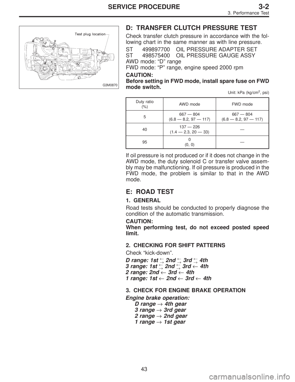
G3M0870
D: TRANSFER CLUTCH PRESSURE TEST
Check transfer clutch pressure in accordance with the fol-
lowing chart in the same manner as with line pressure.
ST 499897700 OIL PRESSURE ADAPTER SET
ST 498575400 OIL PRESSURE GAUGE ASSY
AWD mode:“D”range
FWD mode:“P”range, engine speed 2000 rpm
CAUTION:
Before setting in FWD mode, install spare fuse on FWD
mode switch.
Unit: kPa (kg/cm2, psi)
Duty ratio
(%)AWD mode FWD mode
5667—804
(6.8—8.2, 97—117)667—804
(6.8—8.2, 97—117)
40137—226
(1.4—2.3, 20—33)—
950
(0, 0)—
If oil pressure is not produced or if it does not change in the
AWD mode, the duty solenoid C or transfer valve assem-
bly may be malfunctioning. If oil pressure is produced in the
FWD mode, the problem is similar to that in the AWD
mode.
E: ROAD TEST
1. GENERAL
Road tests should be conducted to properly diagnose the
condition of the automatic transmission.
CAUTION:
When performing test, do not exceed posted speed
limit.
2. CHECKING FOR SHIFT PATTERNS
Check“kick-down”.
D range: 1st
←
→2nd←
→3rd←
→4th
3 range: 1st←
→2nd←
→3rd←4th
2 range: 2nd←3rd←4th
1 range: 1st←2nd←3rd←4th
3. CHECK FOR ENGINE BRAKE OPERATION
Engine brake operation:
D range→4th gear
3 range→3rd gear
2 range→2nd gear
1 range→1st gear
43
3-2SERVICE PROCEDURE
3. Performance Test
Page 950 of 3342
4. CHECK FOR THE AWD FUNCTION
If“tight-corner braking”occurs when the steering wheel is
fully turned at low speed:
1) Determine the applicable trouble code and check the
corresponding duty solenoid C (transfer) for improper
operation.
2) If the solenoid is operating properly, check transfer
clutch pressure.
3) If oil pressure is normal but“tight-corner braking”
occurs:
Check the transfer control valve for sticking, and the trans-
fer clutch facing for wear.
44
3-2SERVICE PROCEDURE
3. Performance Test
Page 965 of 3342

B: ASSEMBLY OF OVERALL TRANSMISSION
1. TORQUE CONVERTER CLUTCH CASE SECTION
1) Check the appearance of each component and clean.
CAUTION:
Make sure each part is free of harmful cuts, damage
and other faults.
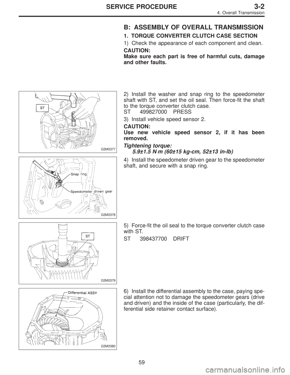
G3M0377
2) Install the washer and snap ring to the speedometer
shaft with ST, and set the oil seal. Then force-fit the shaft
to the torque converter clutch case.
ST 499827000 PRESS
3) Install vehicle speed sensor 2.
CAUTION:
Use new vehicle speed sensor 2, if it has been
removed.
Tightening torque:
5.9±1.5 N⋅m (60±15 kg-cm, 52±13 in-lb)
G3M0378
4) Install the speedometer driven gear to the speedometer
shaft, and secure with a snap ring.
G3M0379
5) Force-fit the oil seal to the torque converter clutch case
with ST.
ST 398437700 DRIFT
G3M0380
6) Install the differential assembly to the case, paying spe-
cial attention not to damage the speedometer gears (drive
and driven) and the inside of the case (particularly, the dif-
ferential side retainer contact surface).
59
3-2SERVICE PROCEDURE
4. Overall Transmission
Page 966 of 3342

7) Install the circlip to the axle shaft, insert the shaft into
the differential assembly, and tap it into position with a
plastic hammer.
Thrust play:
Approx. 0.3—0.5 mm (0.012—0.020 in)
CAUTION:
�If no play is felt, check whether the shaft is fully
inserted. If shaft insertion is correct, replace the axle
shaft.
�Be sure to use a new circlip.
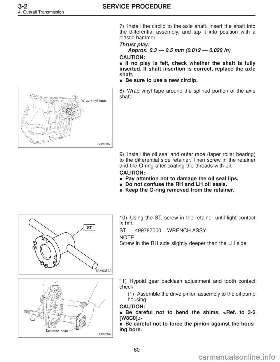
G3M0368
8) Wrap vinyl tape around the splined portion of the axle
shaft.
9) Install the oil seal and outer race (taper roller bearing)
to the differential side retainer. Then screw in the retainer
and the O-ring after coating the threads with oil.
CAUTION:
�Pay attention not to damage the oil seal lips.
�Do not confuse the RH and LH oil seals.
�Keep the O-ring removed from the retainer.
B3M0352A
10) Using the ST, screw in the retainer until light contact
is felt.
ST 499787000 WRENCH ASSY
NOTE:
Screw in the RH side slightly deeper than the LH side.
G3M0382
11) Hypoid gear backlash adjustment and tooth contact
check
(1) Assemble the drive pinion assembly to the oil pump
housing.
CAUTION:
�Be careful not to bend the shims.
[W8C0].>
�Be careful not to force the pinion against the hous-
ing bore.
60
3-2SERVICE PROCEDURE
4. Overall Transmission
Page 969 of 3342

(8) Apply red lead evenly to the surfaces of three or
four teeth of the crown gear. Rotate the drive pinion in
the forward and reverse directions several times. Then
remove the oil pump housing, and check the tooth con-
tact pattern.
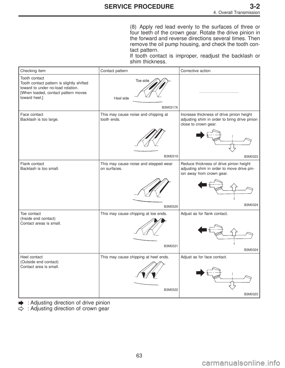
If tooth contact is improper, readjust the backlash or
shim thickness.
Checking item Contact pattern Corrective action
Tooth contact
Tooth contact pattern is slightly shifted
toward to under no-load rotation.
[When loaded, contact pattern moves
toward heel.]
B3M0317A
Face contact
Backlash is too large.This may cause noise and chipping at
tooth ends.
B3M0319
Increase thickness of drive pinion height
adjusting shim in order to bring drive pinion
close to crown gear.
B3M0323
Flank contact
Backlash is too small.This may cause noise and stepped wear
on surfaces.
B3M0320
Reduce thickness of drive pinion height
adjusting shim in order to move drive pin-
ion away from crown gear.
B3M0324
Toe contact
(Inside end contact)
Contact areas is small.This may cause chipping at toe ends.
B3M0321
Adjust as for flank contact.
B3M0324
Heel contact
(Outside end contact)
Contact area is small.This may cause chipping at heel ends.
B3M0322
Adjust as for face contact.
B3M0323
: Adjusting direction of drive pinion
: Adjusting direction of crown gear
63
3-2SERVICE PROCEDURE
4. Overall Transmission
Page 995 of 3342
G3M0906
5) Temporarily assemble lower valve body to upper valve
body.
CAUTION:
Be careful not to drop the upper body interior steel
ball, or the lower body interior filter, orifice check
spring, or orifice check valve.
B3M0406A
6) Install the duty solenoid B and the four brackets.
7) Tighten twenty seven bolts & washers and two reamer
bolts.
Tightening torque:
T1: 8±1 N⋅m (0.8±0.1 kg-m, 5.8±0.7 ft-lb)
T2: 11.3±1.5 N⋅m (1.15±0.15 kg-m, 8.3±1.1 ft-lb)
Unit: mm (in)
abcde
Length 70 (2.76) 50 (1.97) 33 (1.30) 27 (1.06) 28 (1.10)
Numbers 2 6 16 1 2
G3M0864
8) Install the shift solenoid and duty solenoid A.
a length : 16 mm (0.63 in)
b length : 27 mm (1.06 in)
Tightening torque:
8±1 N⋅m (0.8±0.1 kg-m, 5.8±0.7 ft-lb)
G3M0445
7. Oil Pump Assembly
A: DISASSEMBLY
1) Remove the oil seal retainer.
Also remove the O-ring and oil seal (air breather).
89
3-2SERVICE PROCEDURE
6. Control Valve Body - 7. Oil Pump Assembly
Page 996 of 3342
G3M0906
5) Temporarily assemble lower valve body to upper valve
body.
CAUTION:
Be careful not to drop the upper body interior steel
ball, or the lower body interior filter, orifice check
spring, or orifice check valve.
B3M0406A
6) Install the duty solenoid B and the four brackets.
7) Tighten twenty seven bolts & washers and two reamer
bolts.
Tightening torque:
T1: 8±1 N⋅m (0.8±0.1 kg-m, 5.8±0.7 ft-lb)
T2: 11.3±1.5 N⋅m (1.15±0.15 kg-m, 8.3±1.1 ft-lb)
Unit: mm (in)
abcde
Length 70 (2.76) 50 (1.97) 33 (1.30) 27 (1.06) 28 (1.10)
Numbers 2 6 16 1 2
G3M0864
8) Install the shift solenoid and duty solenoid A.
a length : 16 mm (0.63 in)
b length : 27 mm (1.06 in)
Tightening torque:
8±1 N⋅m (0.8±0.1 kg-m, 5.8±0.7 ft-lb)
G3M0445
7. Oil Pump Assembly
A: DISASSEMBLY
1) Remove the oil seal retainer.
Also remove the O-ring and oil seal (air breather).
89
3-2SERVICE PROCEDURE
6. Control Valve Body - 7. Oil Pump Assembly
Page 999 of 3342
G3M0454
2) Install the vane ring, rotor and vanes into the housing
in this sequence.
G3M0455
3) Install the return spring and retainer between the hous-
ing and cam ring.
G3M0456
4) Install the control piston to the oil pump housing.
NOTE:
Fit the seal in the piston groove, with the red seals facing
the top side. (Two side seals and one plain seal are
attached.)
5) Set the rotor at the center of the housing bore. Apply
ATF abundantly to each rotary portion.
G3M0446
6) Install the oil pump cover.
Tightening torque:
25±2 N⋅m (2.5±0.2 kg-m, 18.1±1.4 ft-lb)
NOTE:
�Align both pivots with the pivot holes of the cover, and
install the cover being careful not to apply undue force to
the pivots.
�After assembling, turn the oil pump shaft to check for
smooth rotation of the rotor.
G3M0449
NOTE:
�Install the oil seal retainer and seal rings (R) and (H)
after adjusting the drive pinion backlash and tooth contact.
92
3-2SERVICE PROCEDURE
7. Oil Pump Assembly