Page 1236 of 3342
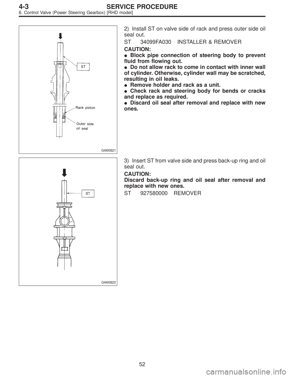
G4M0821
2) Install ST on valve side of rack and press outer side oil
seal out.
ST 34099FA030 INSTALLER & REMOVER
CAUTION:
�Block pipe connection of steering body to prevent
fluid from flowing out.
�Do not allow rack to come in contact with inner wall
of cylinder. Otherwise, cylinder wall may be scratched,
resulting in oil leaks.
�Remove holder and rack as a unit.
�Check rack and steering body for bends or cracks
and replace as required.
�Discard oil seal after removal and replace with new
ones.
G4M0822
3) Insert ST from valve side and press back-up ring and oil
seal out.
CAUTION:
Discard back-up ring and oil seal after removal and
replace with new ones.
ST 927580000 REMOVER
52
4-3SERVICE PROCEDURE
6. Control Valve (Power Steering Gearbox) [RHD model]
Page 1237 of 3342
G4M0823
4) Using ST1 and ST2, repair cylinder’s clinched sections.
ST1 34099FA080 PUNCH
ST2 34099FA070 BASE
G4M0889
5) If cylinder edge is deformed in a convex shape, repair
using an oil stone.
G4M0824
C: REPLACEMENT OF SEAL AND PACKING
1. VALVE HOUSING OIL SEAL
�Removal
1) After removing dust cover, extract pinion and valve from
valve housing.
CAUTION:
�If pinion and valve is difficult to remove, use a press.
�Discard Y-packing after removal and replace with a
new one.
�Check rotor for bends and serrations for damage
and replace as required.
53
4-3SERVICE PROCEDURE
6. Control Valve (Power Steering Gearbox) [RHD model]
Page 1248 of 3342
 Remove clamp E from pipes C and D.
5) Remove flare nuts from control valve of gearbox
assembly, and then disconnect pipe C⋅D.
CAUTION:
�When disconnecting pipe C⋅D, use two wrenches to")
B4M0672A
4) Remove clamp E from pipes C and D.
5) Remove flare nuts from control valve of gearbox
assembly, and then disconnect pipe C⋅D.
CAUTION:
�When disconnecting pipe C⋅D, use two wrenches to
prevent deformities.
�Be careful to keep pipe connections free from for-
eign matter.
B4M1159A
6) Remove bolt A.
Disconnect pipe C from oil pump. Disconnect pipe D from
oil tank.
CAUTION:
�Do not allow fluid from the hose end to come into
contact with pulley belt.
�To prevent foreign matter from entering the hose
and pipe, cover the open ends of them with a clean
cloth.
B: CHECK
Check all disassembled parts for wear, damage or other
abnormalities. Repair or replace faulty parts as required.
Part name Inspection Remedy
Pipe�O-ring fitting surface for
damage
�Nut for damage
�Pipe for damageReplace with new one.
Clamp
�Clamps for weak
clamping forceReplace with new one.
Clamp E
Hose�Flared surface for
damage
�Flare nut for damage
�Outer surface for cracks
�Outer surface for wear
�Clip for damage
�End coupling or adapter
for degradationReplace with new one.
64
4-3SERVICE PROCEDURE
7. Pipe Assembly (Power Steering System)
Page 1249 of 3342
B4M1159A
C: ASSEMBLY
1. LHD MODEL
1) Interconnect pipes C and D.
Tightening torque:
Joint nut
15±5 N⋅m (1.5±0.5 kg-m, 10.8±3.6 ft-lb)
CAUTION:
Visually check that hose between tank and pipe D is
free from bending or twisting.
2) Connect pipe D from oil tank.
3) Connect pipe C from oil pump.
CAUTION:
Use a new gasket.
Tightening torque:
34±5 N⋅m (3.5±0.5 kg-m, 25.3±3.6 ft-lb)
4) Tighten bolt A.
Tightening torque:
13±3 N⋅m (1.3±0.3 kg-m, 9.4±2.2 ft-lb)
G4M0165
5) Temporarily connect pipes C and D to pipes (on the
gearbox side).
65
4-3SERVICE PROCEDURE
7. Pipe Assembly (Power Steering System)
Page 1251 of 3342
G4M0167
13) Finally check clearance between pipes and/or hoses,
as shown above.
If clearance between cruise control pump and power steer-
ing hose is less than 10 mm (0.39 in), proceed as follows:
(1) Move clamped section�
A(refer to figure above.)
down to a point where pipe is close to crossmember.
Pipe-to-crossmember clearance:
10 mm (0.39 in), min.
(2) Check that clearance between cruise control pump
and power steering hose is at least 10 mm (0.39 in). If
it is not, bend section�
Bdown until a clearance of at
least 10 mm (0.39 in) is obtained.
B4M1159A
2. RHD MODEL
1) Interconnect pipes C and D.
Tightening torque:
Joint nut
15±5 N⋅m (1.5±0.5 kg-m, 10.8±3.6 ft-lb)
CAUTION:
Visually check that hose between tank and pipe D is
free from bending or twisting.
2) Connect pipe D from oil tank.
67
4-3SERVICE PROCEDURE
7. Pipe Assembly (Power Steering System)
Page 1255 of 3342
 Place oil pump in a vise, remove two bolts from oil tank
and detach oil tank.
CAUTION:
Do not place oil pump directly in the vise; use soft
pads and hold oil pump lightly to protect the p")
B4M0561A
10) Place oil pump in a vise, remove two bolts from oil tank
and detach oil tank.
CAUTION:
Do not place oil pump directly in the vise; use soft
pads and hold oil pump lightly to protect the pump.
11) Remove O-ring from oil pump.
12) Remove stay from oil pump. (2500 cc model only)
B: CHECK
In accordance with the following table, check all removed
parts for wear and damage, and make repair or replace-
ment if necessary.
No. Parts Inspection Corrective action
1 Oil pump (Exterior)(1) Crack, damage or oil leakage Replace oil pump with a new one.
(2) Play of pulley shaftMeasure radial play and axial play.
If any of these exceeds the service limit,
replace oil pump with a new one.
4-3 [W8B1].>
2 Pulley(1) Damage Replace it with a new one.
(2) BendMeasure V ditch deflection.
If it exceeds the service limit, replace
pulley with a new one.
[W8B1].>
3 Cap Crack or damage Replace it with a new one.
4 Strainer(1) Clogging with dirt Wash it.
(2) Breakage Replace it with a new one.
5 Oil pump (Interior)(1) Defect or burning of vane pumpCheck resistance to rotation of pulley.
If it is past the service limit, replace oil
pump with a new one.
[W8B1].>
(2) Bend in the shaft or damage to
bearingOil pump emits a noise that is markedly
different in tone and loudness from a
sound of a new oil pump when turning with
a string put around its pulley, replace oil
pump with a new one.
6 O-ring Crack or deterioration Replace it with a new one.
7 Oil tank Crack, damage or oil leakage Replace it with a new one.
8 Bracket Crack or damage Replace it with a new one.
71
4-3SERVICE PROCEDURE
8. Oil Pump (Power Steering System)
Page 1262 of 3342
 Check
(1) When reassembly procedures have been
completed, turn shaft by hand to ensure it turns
smoothly. If it binds or other unusual conditions are
evident, disassemble again and check for foreig")
6) Check
(1) When reassembly procedures have been
completed, turn shaft by hand to ensure it turns
smoothly. If it binds or other unusual conditions are
evident, disassemble again and check for foreign mat-
ter trapped on sliding surfaces and improper installa-
tion. Eliminate the cause of trouble.
(2) Check followings by referring to“CHECK”article.
�Excessive play in pulley shaft
�Ditch deflection of pulley
�Resistance to rotation of pulley
�Measurement of generated oil pressure
F: INSTALLATION
1) Install bracket on engine.
Tightening torque:
22±2 N⋅m (2.2±0.2 kg-m, 15.9±1.4 ft-lb)
2) Install oil pump on oil tank as follows outside the
vehicle:
NOTE:
Prior to installation, make sure that all oil is removed from
oil pump, oil tank and pipe.
B4M0562A
3) Place oil pump in vise.
CAUTION:
Do not place oil pump directly in vise; use soft pads
and hold oil pump lightly to protect it.
4) Install O-ring on oil pump.
CAUTION:
Discard old O-ring and replace with a new one.
5) Install oil tank on oil pump.
Tightening torque:
Bolt C: 15.7±2.4 N⋅m
(1.60±0.24 kg-m, 11.58±1.77 ft-lb)
Bolt D: 18.1±2.5 N⋅m
(1.85±0.25 kg-m, 13.35±1.84 ft-lb)
CAUTION:
Discard old seal washer and replace with a new one.
78
4-3SERVICE PROCEDURE
8. Oil Pump (Power Steering System)
Page 1264 of 3342
 Feed")
9. Power Steering Fluid
A: RECOMMENDED AIR BLEEDING AND
POWER STEERING FLUID
Recommended power steering fluid Manufacturer
ATF DEXRON II or ATF DEXRON IIEB.P.
CALTEX
CASTROL
MOBIL
SHELL
TEXACO
1) Feed the specified fluid with its level being about 5 cm
(2.0 in) lower than the mouth of tank.
2) Continue to turn steering wheel slowly from lock to lock
until bubbles stop appearing in the tank while keeping the
fluid at that level.
3) In case air is absorbed to deliver bubbles into piping
because the fluid level is lower, leave it about half an hour
and then do the step 2) all over again.
4) Start, and idle the engine.
5) Continue to turn steering wheel slowly from lock to lock
again until bubbles stop appearing in the tank while keep-
ing the fluid at that level.
It is normal that bubbles stop appearing after three times
turning of steering wheel.
6) In case bubbles do not stop appearing in the tank, leave
it about half an hour and then do the step 5) all over again.
7) Stop the engine, and take out safety stands after jack-
ing up vehicle again.
Then lower the vehicle, and idle the engine.
8) Continue to turn steering wheel from lock to lock until
bubbles stop appearing and change of the fluid level is
within 3 mm (0.12 in).
9) In case the following happens, leave it about half an
hour and then do step 8) again.
(1) The fluid level changes over 3 mm (0.12 in).
(2) Bubbles remain on the upper surface of the fluid.
(3) Grinding noise is generated from oil pump.
10) Check the fluid leakage at flare nuts after turning
steering wheel from lock to lock with engine running.
CAUTION:
�Before checking, wipe off any fluid on flare nuts and
piping.
�In case the fluid leaks from flare nut, it is caused by
dust (or the like) and/or damage between flare and
tapered seat in piping.
�So remove the flare nut, tighten again it to the speci-
fied torque after cleaning flare and tapered seat. If flare
or tapered seat is damaged, replace it with a new one.
11) Inspect fluid level on flat and level surface with engine
“OFF”by indicator of filler cap.
80
4-3SERVICE PROCEDURE
9. Power Steering Fluid
 Using ST1 and ST2, repair cylinder’s clinched sections.
ST1 34099FA080 PUNCH
ST2 34099FA070 BASE
G4M0889
5) If cylinder edge is deformed in a convex shape, repair
using an oil stone.
G4M0")
 Interconnect pipes C and D.
Tightening torque:
Joint nut
15±5 N⋅m (1.5±0.5 kg-m, 10.8±3.6 ft-lb)
CAUTION:
Visually check that hose between tank and pipe D is")
 Finally check clearance between pipes and/or hoses,
as shown above.
If clearance between cruise control pump and power steer-
ing hose is less than 10 mm (0.39 in), proceed as follows:
(1)")