Page 1476 of 3342
8. Leak Testing
The following points should be kept in mind when conduct-
ing a refrigerant leak test.
1) The A/C system to be tested must have an adequate
refrigerant charge to begin with.
2) The area where the leak test is conducted must be free
of wind and drafts, with still air being the ideal condition.
3) The atmosphere where the leak test is conducted must
be free of refrigerant contamination.
4) Operate the A/C system for approx. 10 minutes, then
turn the engine off an begin the leak test.
5) Refrigerant gas is heavier than air, therefore always
hold the probe below the connection being tested.
6) When checking for a leak along a length of hose or
tube, the leak detector probe must be moved slowly,
approx. 25 mm (1 in) per second making sure probe does
not come in contact with the component being tested.
7) When checking for a leak at a certain point, the leak
detector probe must be held at that point for at least 5
seconds.
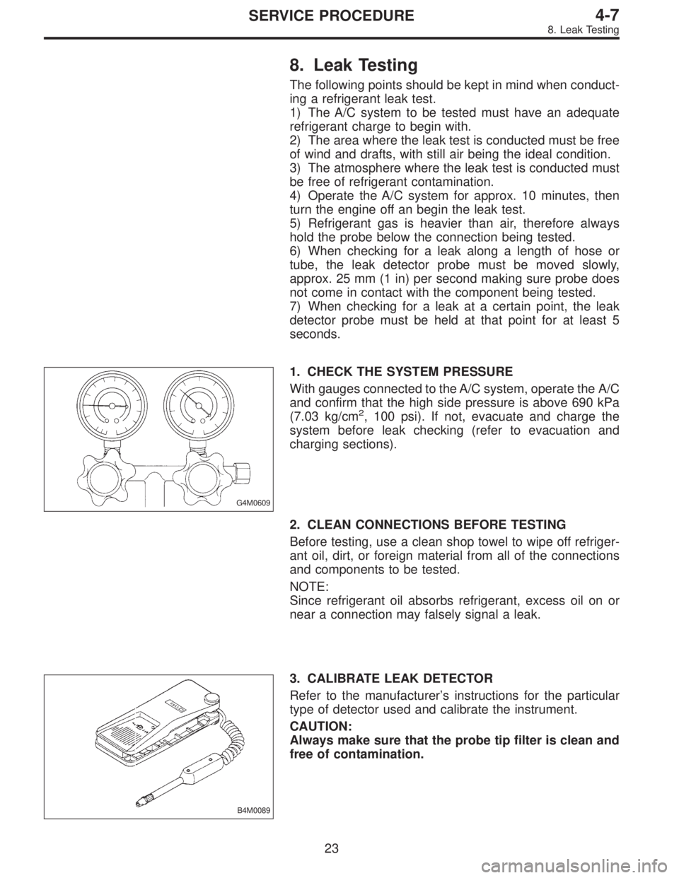
G4M0609
1. CHECK THE SYSTEM PRESSURE
With gauges connected to the A/C system, operate the A/C
and confirm that the high side pressure is above 690 kPa
(7.03 kg/cm
2, 100 psi). If not, evacuate and charge the
system before leak checking (refer to evacuation and
charging sections).
2. CLEAN CONNECTIONS BEFORE TESTING
Before testing, use a clean shop towel to wipe off refriger-
ant oil, dirt, or foreign material from all of the connections
and components to be tested.
NOTE:
Since refrigerant oil absorbs refrigerant, excess oil on or
near a connection may falsely signal a leak.
B4M0089
3. CALIBRATE LEAK DETECTOR
Refer to the manufacturer’s instructions for the particular
type of detector used and calibrate the instrument.
CAUTION:
Always make sure that the probe tip filter is clean and
free of contamination.
23
4-7SERVICE PROCEDURE
8. Leak Testing
Page 1477 of 3342
G4M0612
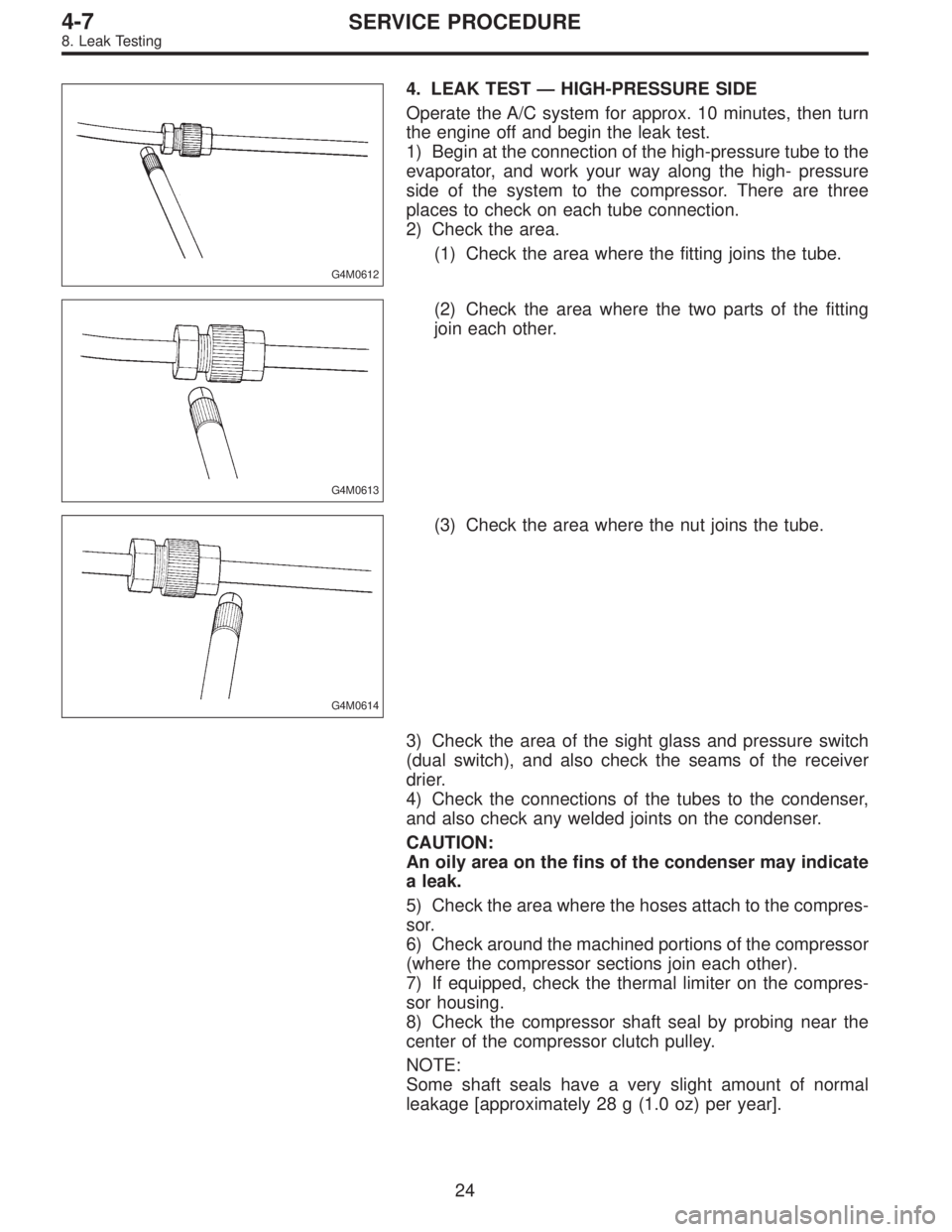
4. LEAK TEST — HIGH-PRESSURE SIDE
Operate the A/C system for approx. 10 minutes, then turn
the engine off and begin the leak test.
1) Begin at the connection of the high-pressure tube to the
evaporator, and work your way along the high- pressure
side of the system to the compressor. There are three
places to check on each tube connection.
2) Check the area.
(1) Check the area where the fitting joins the tube.
G4M0613
(2) Check the area where the two parts of the fitting
join each other.
G4M0614
(3) Check the area where the nut joins the tube.
3) Check the area of the sight glass and pressure switch
(dual switch), and also check the seams of the receiver
drier.
4) Check the connections of the tubes to the condenser,
and also check any welded joints on the condenser.
CAUTION:
An oily area on the fins of the condenser may indicate
a leak.
5) Check the area where the hoses attach to the compres-
sor.
6) Check around the machined portions of the compressor
(where the compressor sections join each other).
7) If equipped, check the thermal limiter on the compres-
sor housing.
8) Check the compressor shaft seal by probing near the
center of the compressor clutch pulley.
NOTE:
Some shaft seals have a very slight amount of normal
leakage [approximately 28 g (1.0 oz) per year].
24
4-7SERVICE PROCEDURE
8. Leak Testing
Page 1479 of 3342
G4M0619
8. CHECK THE SERVICE PORT CAPS
Visually inspect the inside of the service port caps. Make
sure the rubber seal is in place on the inside of the caps.
Disconnect the gauges from the vehicle and install the
service port caps.
9. Lubrication
1. SYSTEM OIL STABILIZATION
Prior to opening the refrigerant system for repairs (except
compressor seizure) the system must be stabilized for cor-
rect oil replenishment.
Follow these procedures:
1) Engine speed set to 1,500 rpm
2) A/C“ON”
3) Air source to recirculate
4) Blower in 4th or high speed position
�Make sure the air entering the evaporator is above
26.7°C (80°F).
�The discharge (high) side pressure must be above
588 kPa (6 kg/cm
2, 85 psi).
5) Operate the A/C for 10 minutes.
2. SYSTEM DISCHARGE
Slowly, discharge the system starting with the high- pres-
sure side until the pressure drops below 345 kPa (3.52
kg/cm
2, 50 psi), then open the low-pressure side.
26
4-7SERVICE PROCEDURE
8. Leak Testing - 9. Lubrication
Page 1480 of 3342
G4M0619
8. CHECK THE SERVICE PORT CAPS
Visually inspect the inside of the service port caps. Make
sure the rubber seal is in place on the inside of the caps.
Disconnect the gauges from the vehicle and install the
service port caps.
9. Lubrication
1. SYSTEM OIL STABILIZATION
Prior to opening the refrigerant system for repairs (except
compressor seizure) the system must be stabilized for cor-
rect oil replenishment.
Follow these procedures:
1) Engine speed set to 1,500 rpm
2) A/C“ON”
3) Air source to recirculate
4) Blower in 4th or high speed position
�Make sure the air entering the evaporator is above
26.7°C (80°F).
�The discharge (high) side pressure must be above
588 kPa (6 kg/cm
2, 85 psi).
5) Operate the A/C for 10 minutes.
2. SYSTEM DISCHARGE
Slowly, discharge the system starting with the high- pres-
sure side until the pressure drops below 345 kPa (3.52
kg/cm
2, 50 psi), then open the low-pressure side.
26
4-7SERVICE PROCEDURE
8. Leak Testing - 9. Lubrication
Page 1484 of 3342
11. Compressor
Compressor is a swash plate type. When trouble occurs,
replace compressor as a single unit.
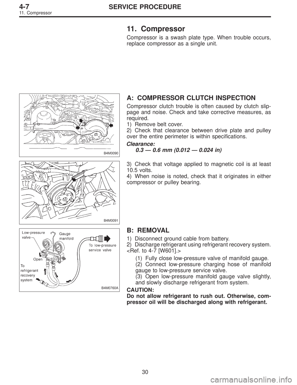
B4M0090
A: COMPRESSOR CLUTCH INSPECTION
Compressor clutch trouble is often caused by clutch slip-
page and noise. Check and take corrective measures, as
required.
1) Remove belt cover.
2) Check that clearance between drive plate and pulley
over the entire perimeter is within specifications.
Clearance:
0.3 — 0.6 mm (0.012 — 0.024 in)
B4M0091
3) Check that voltage applied to magnetic coil is at least
10.5 volts.
4) When noise is noted, check that it originates in either
compressor or pulley bearing.
B4M0760A
B: REMOVAL
1) Disconnect ground cable from battery.
2) Discharge refrigerant using refrigerant recovery system.
(1) Fully close low-pressure valve of manifold gauge.
(2) Connect low-pressure charging hose of manifold
gauge to low-pressure service valve.
(3) Open low-pressure manifold gauge valve slightly,
and slowly discharge refrigerant from system.
CAUTION:
Do not allow refrigerant to rush out. Otherwise, com-
pressor oil will be discharged along with refrigerant.
30
4-7SERVICE PROCEDURE
11. Compressor
Page 1487 of 3342
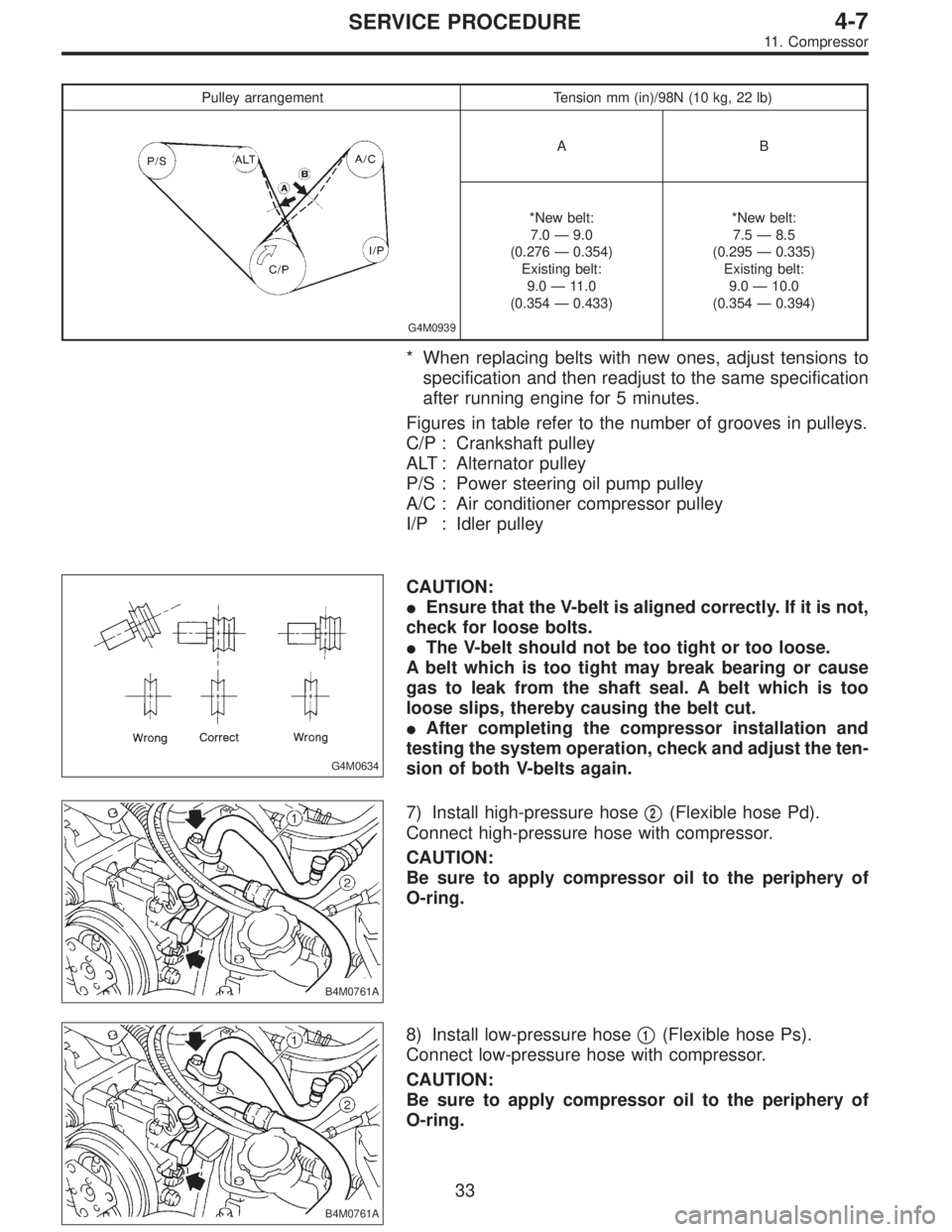
Pulley arrangement Tension mm (in)/98N (10 kg, 22 lb)
G4M0939
AB
*New belt:
7.0—9.0
(0.276—0.354)
Existing belt:
9.0—11.0
(0.354—0.433)*New belt:
7.5—8.5
(0.295—0.335)
Existing belt:
9.0—10.0
(0.354—0.394)
* When replacing belts with new ones, adjust tensions to
specification and then readjust to the same specification
after running engine for 5 minutes.
Figures in table refer to the number of grooves in pulleys.
C/P : Crankshaft pulley
ALT : Alternator pulley
P/S : Power steering oil pump pulley
A/C : Air conditioner compressor pulley
I/P : Idler pulley
G4M0634
CAUTION:
�Ensure that the V-belt is aligned correctly. If it is not,
check for loose bolts.
�The V-belt should not be too tight or too loose.
A belt which is too tight may break bearing or cause
gas to leak from the shaft seal. A belt which is too
loose slips, thereby causing the belt cut.
�After completing the compressor installation and
testing the system operation, check and adjust the ten-
sion of both V-belts again.
B4M0761A
7) Install high-pressure hose�2(Flexible hose Pd).
Connect high-pressure hose with compressor.
CAUTION:
Be sure to apply compressor oil to the periphery of
O-ring.
B4M0761A
8) Install low-pressure hose�1(Flexible hose Ps).
Connect low-pressure hose with compressor.
CAUTION:
Be sure to apply compressor oil to the periphery of
O-ring.
33
4-7SERVICE PROCEDURE
11. Compressor
Page 1490 of 3342
B4M0098A
8) The condenser should be installed in the reverse order
in which it was removed.
When installing the condenser, pay attention to the follow-
ing:
CAUTION:
Before connecting the pipe, be sure to apply oil to the
periphery of O-ring.
NOTE:
After installing condenser, ensure that guide on lower side
of condenser is inserted into hole in radiator panel. Tighten
attaching bolts.
9) Charge refrigerant.
B: INSPECTION
1) Make sure the condenser fins are free from dust and
insects. If the fins are clogged, clean by blowing air or
water through them.
NOTE:
To prevent dust and water from getting into the condenser,
this work must be done when the condenser is installed in
an actual vehicle.
2) Check the condenser to see if it shows any sign of oil.
Should oil ooze or gas leak from the condenser replace it
with a new one.
35
4-7SERVICE PROCEDURE
12. Condenser
Page 1499 of 3342
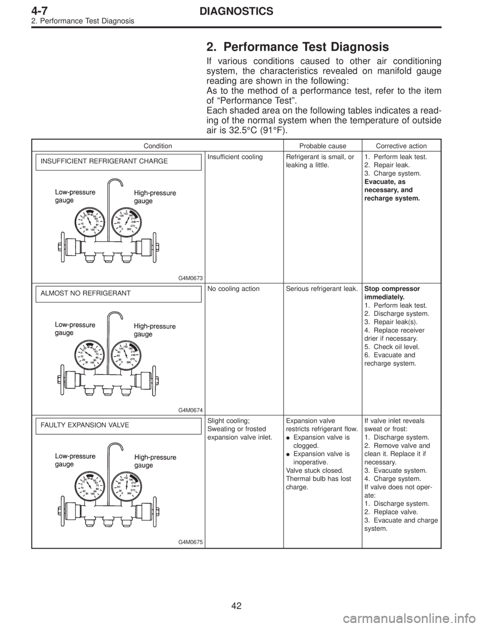
2. Performance Test Diagnosis
If various conditions caused to other air conditioning
system, the characteristics revealed on manifold gauge
reading are shown in the following:
As to the method of a performance test, refer to the item
of“Performance Test”.
Each shaded area on the following tables indicates a read-
ing of the normal system when the temperature of outside
air is 32.5°C (91°F).
Condition Probable cause Corrective action
INSUFFICIENT REFRIGERANT CHARGE
G4M0673
Insufficient cooling Refrigerant is small, or
leaking a little.1. Perform leak test.
2. Repair leak.
3. Charge system.
Evacuate, as
necessary, and
recharge system.
ALMOST NO REFRIGERANT
G4M0674
No cooling action Serious refrigerant leak.Stop compressor
immediately.
1. Perform leak test.
2. Discharge system.
3. Repair leak(s).
4. Replace receiver
drier if necessary.
5. Check oil level.
6. Evacuate and
recharge system.
FAULTY EXPANSION VALVE
G4M0675
Slight cooling;
Sweating or frosted
expansion valve inlet.Expansion valve
restricts refrigerant flow.
�Expansion valve is
clogged.
�Expansion valve is
inoperative.
Valve stuck closed.
Thermal bulb has lost
charge.If valve inlet reveals
sweat or frost:
1. Discharge system.
2. Remove valve and
clean it. Replace it if
necessary.
3. Evacuate system.
4. Charge system.
If valve does not oper-
ate:
1. Discharge system.
2. Replace valve.
3. Evacuate and charge
system.
42
4-7DIAGNOSTICS
2. Performance Test Diagnosis