Page 1501 of 3342
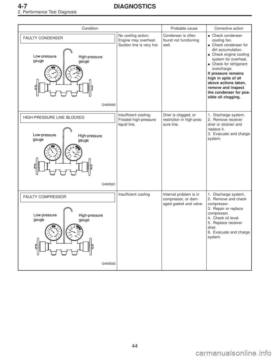
Condition Probable cause Corrective action
FAULTY CONDENSER
G4M0680
No cooling action;
Engine may overheat.
Suction line is very hot.Condenser is often
found not functioning
well.�Check condenser
cooling fan.
�Check condenser for
dirt accumulation.
�Check engine cooling
system for overheat.
�Check for refrigerant
overcharge.
If pressure remains
high in spite of all
above actions taken,
remove and inspect
the condenser for pos-
sible oil clogging.
HIGH-PRESSURE LINE BLOCKED
G4M0681
Insufficient cooling;
Frosted high-pressure
liquid line.Drier is clogged, or
restriction in high-pres-
sure line.1. Discharge system.
2. Remove receiver
drier or strainer and
replace it.
3. Evacuate and charge
system.
FAULTY COMPRESSOR
G4M0682
Insufficient cooling Internal problem is in
compressor, or dam-
aged gasket and valve.1. Discharge system.
2. Remove and check
compressor.
3. Repair or replace
compressor.
4. Check oil level.
5. Replace receiver
drier.
6. Evacuate and charge
system.
44
4-7DIAGNOSTICS
2. Performance Test Diagnosis
Page 1555 of 3342
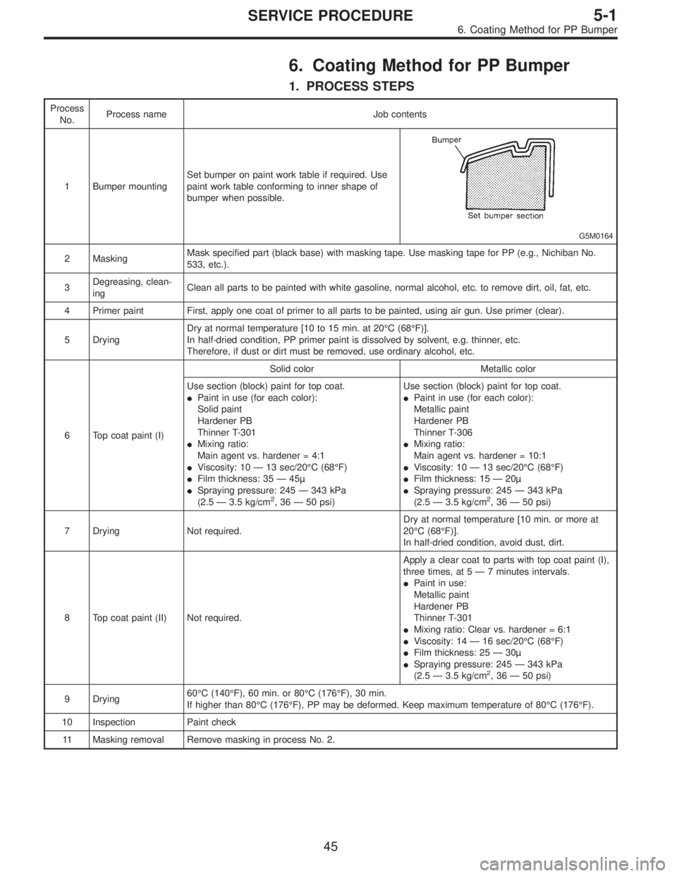
6. Coating Method for PP Bumper
1. PROCESS STEPS
Process
No.Process name Job contents
1 Bumper mountingSet bumper on paint work table if required. Use
paint work table conforming to inner shape of
bumper when possible.
G5M0164
2 MaskingMask specified part (black base) with masking tape. Use masking tape for PP (e.g., Nichiban No.
533, etc.).
3Degreasing, clean-
ingClean all parts to be painted with white gasoline, normal alcohol, etc. to remove dirt, oil, fat, etc.
4 Primer paint First, apply one coat of primer to all parts to be painted, using air gun. Use primer (clear).
5 DryingDry at normal temperature [10 to 15 min. at 20°C (68°F)].
In half-dried condition, PP primer paint is dissolved by solvent, e.g. thinner, etc.
Therefore, if dust or dirt must be removed, use ordinary alcohol, etc.
6 Top coat paint (I)Solid color Metallic color
Use section (block) paint for top coat.
�Paint in use (for each color):
Solid paint
Hardener PB
Thinner T-301
�Mixing ratio:
Main agent vs. hardener = 4:1
�Viscosity: 10—13 sec/20°C (68°F)
�Film thickness: 35—45µ
�Spraying pressure: 245—343 kPa
(2.5—3.5 kg/cm
2,36—50 psi)Use section (block) paint for top coat.
�Paint in use (for each color):
Metallic paint
Hardener PB
Thinner T-306
�Mixing ratio:
Main agent vs. hardener = 10:1
�Viscosity: 10—13 sec/20°C (68°F)
�Film thickness: 15—20µ
�Spraying pressure: 245—343 kPa
(2.5—3.5 kg/cm2,36—50 psi)
7 Drying Not required.Dry at normal temperature [10 min. or more at
20°C (68°F)].
In half-dried condition, avoid dust, dirt.
8 Top coat paint (II) Not required.Apply a clear coat to parts with top coat paint (I),
three times, at 5—7 minutes intervals.
�Paint in use:
Metallic paint
Hardener PB
Thinner T-301
�Mixing ratio: Clear vs. hardener = 6:1
�Viscosity: 14—16 sec/20°C (68°F)
�Film thickness: 25—30µ
�Spraying pressure: 245—343 kPa
(2.5—3.5 kg/cm
2,36—50 psi)
9 Drying60°C (140°F), 60 min. or 80°C (176°F), 30 min.
If higher than 80°C (176°F), PP may be deformed. Keep maximum temperature of 80°C (176°F).
10 Inspection Paint check
11 Masking removal Remove masking in process No. 2.
45
5-1SERVICE PROCEDURE
6. Coating Method for PP Bumper
Page 1656 of 3342
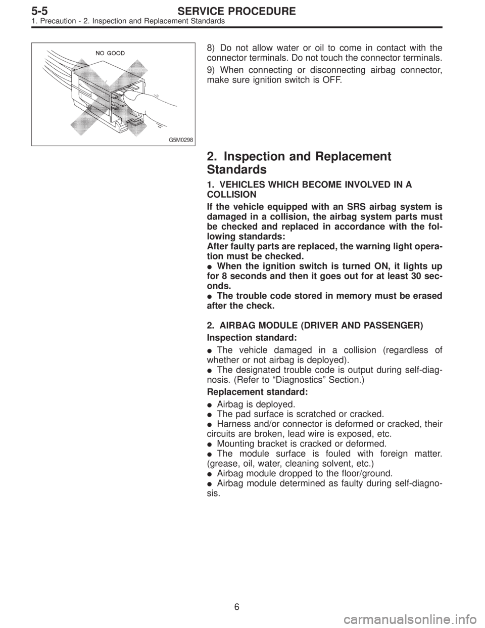
G5M0298
8) Do not allow water or oil to come in contact with the
connector terminals. Do not touch the connector terminals.
9) When connecting or disconnecting airbag connector,
make sure ignition switch is OFF.
2. Inspection and Replacement
Standards
1. VEHICLES WHICH BECOME INVOLVED IN A
COLLISION
If the vehicle equipped with an SRS airbag system is
damaged in a collision, the airbag system parts must
be checked and replaced in accordance with the fol-
lowing standards:
After faulty parts are replaced, the warning light opera-
tion must be checked.
�When the ignition switch is turned ON, it lights up
for 8 seconds and then it goes out for at least 30 sec-
onds.
�The trouble code stored in memory must be erased
after the check.
2. AIRBAG MODULE (DRIVER AND PASSENGER)
Inspection standard:
�The vehicle damaged in a collision (regardless of
whether or not airbag is deployed).
�The designated trouble code is output during self-diag-
nosis. (Refer to“Diagnostics”Section.)
Replacement standard:
�Airbag is deployed.
�The pad surface is scratched or cracked.
�Harness and/or connector is deformed or cracked, their
circuits are broken, lead wire is exposed, etc.
�Mounting bracket is cracked or deformed.
�The module surface is fouled with foreign matter.
(grease, oil, water, cleaning solvent, etc.)
�Airbag module dropped to the floor/ground.
�Airbag module determined as faulty during self-diagno-
sis.
6
5-5SERVICE PROCEDURE
1. Precaution - 2. Inspection and Replacement Standards
Page 1657 of 3342
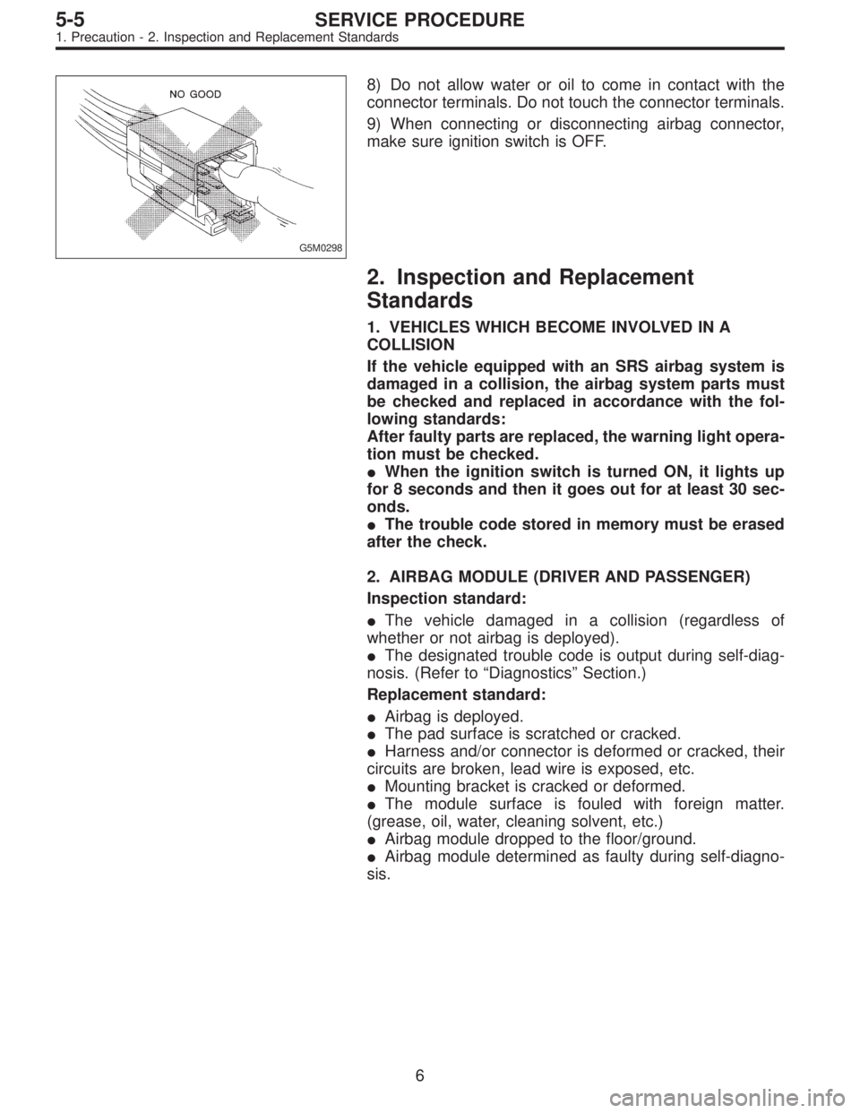
G5M0298
8) Do not allow water or oil to come in contact with the
connector terminals. Do not touch the connector terminals.
9) When connecting or disconnecting airbag connector,
make sure ignition switch is OFF.
2. Inspection and Replacement
Standards
1. VEHICLES WHICH BECOME INVOLVED IN A
COLLISION
If the vehicle equipped with an SRS airbag system is
damaged in a collision, the airbag system parts must
be checked and replaced in accordance with the fol-
lowing standards:
After faulty parts are replaced, the warning light opera-
tion must be checked.
�When the ignition switch is turned ON, it lights up
for 8 seconds and then it goes out for at least 30 sec-
onds.
�The trouble code stored in memory must be erased
after the check.
2. AIRBAG MODULE (DRIVER AND PASSENGER)
Inspection standard:
�The vehicle damaged in a collision (regardless of
whether or not airbag is deployed).
�The designated trouble code is output during self-diag-
nosis. (Refer to“Diagnostics”Section.)
Replacement standard:
�Airbag is deployed.
�The pad surface is scratched or cracked.
�Harness and/or connector is deformed or cracked, their
circuits are broken, lead wire is exposed, etc.
�Mounting bracket is cracked or deformed.
�The module surface is fouled with foreign matter.
(grease, oil, water, cleaning solvent, etc.)
�Airbag module dropped to the floor/ground.
�Airbag module determined as faulty during self-diagno-
sis.
6
5-5SERVICE PROCEDURE
1. Precaution - 2. Inspection and Replacement Standards
Page 1661 of 3342
G5M0299
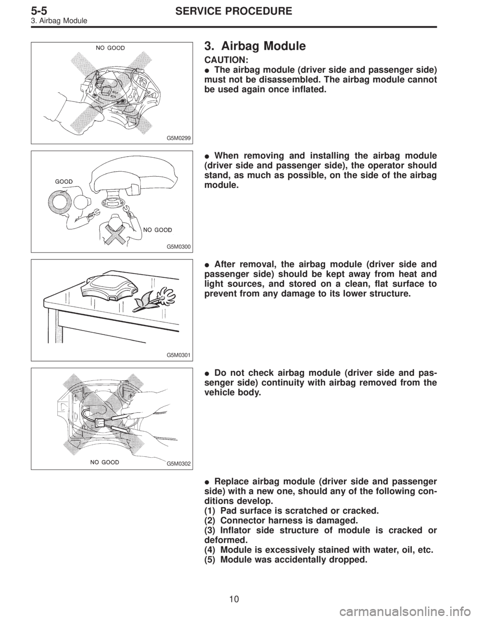
3. Airbag Module
CAUTION:
�The airbag module (driver side and passenger side)
must not be disassembled. The airbag module cannot
be used again once inflated.
G5M0300
�When removing and installing the airbag module
(driver side and passenger side), the operator should
stand, as much as possible, on the side of the airbag
module.
G5M0301
�After removal, the airbag module (driver side and
passenger side) should be kept away from heat and
light sources, and stored on a clean, flat surface to
prevent from any damage to its lower structure.
G5M0302
�Do not check airbag module (driver side and pas-
senger side) continuity with airbag removed from the
vehicle body.
�Replace airbag module (driver side and passenger
side) with a new one, should any of the following con-
ditions develop.
(1) Pad surface is scratched or cracked.
(2) Connector harness is damaged.
(3) Inflator side structure of module is cracked or
deformed.
(4) Module is excessively stained with water, oil, etc.
(5) Module was accidentally dropped.
10
5-5SERVICE PROCEDURE
3. Airbag Module
Page 1680 of 3342
G5M0298
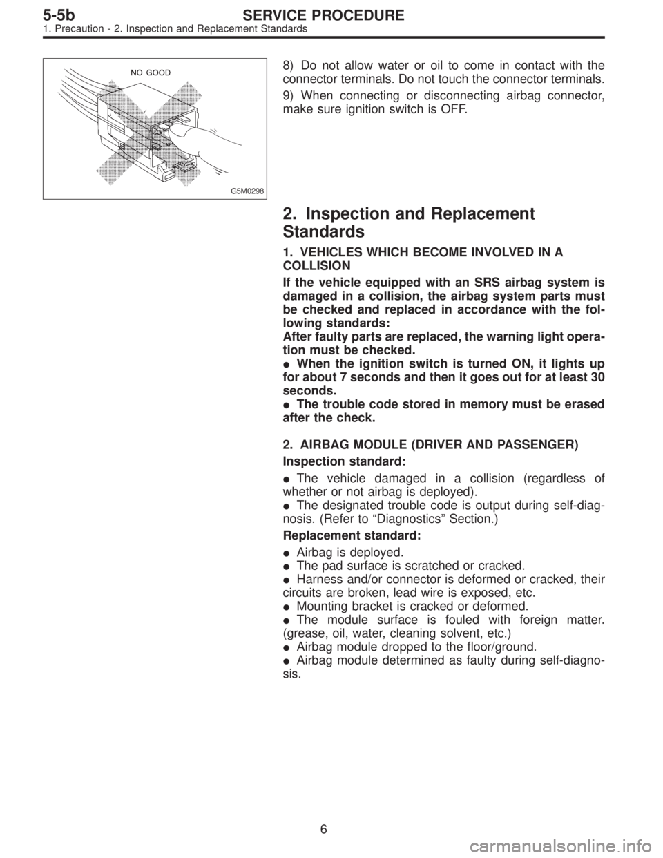
8) Do not allow water or oil to come in contact with the
connector terminals. Do not touch the connector terminals.
9) When connecting or disconnecting airbag connector,
make sure ignition switch is OFF.
2. Inspection and Replacement
Standards
1. VEHICLES WHICH BECOME INVOLVED IN A
COLLISION
If the vehicle equipped with an SRS airbag system is
damaged in a collision, the airbag system parts must
be checked and replaced in accordance with the fol-
lowing standards:
After faulty parts are replaced, the warning light opera-
tion must be checked.
�When the ignition switch is turned ON, it lights up
for about 7 seconds and then it goes out for at least 30
seconds.
�The trouble code stored in memory must be erased
after the check.
2. AIRBAG MODULE (DRIVER AND PASSENGER)
Inspection standard:
�The vehicle damaged in a collision (regardless of
whether or not airbag is deployed).
�The designated trouble code is output during self-diag-
nosis. (Refer to“Diagnostics”Section.)
Replacement standard:
�Airbag is deployed.
�The pad surface is scratched or cracked.
�Harness and/or connector is deformed or cracked, their
circuits are broken, lead wire is exposed, etc.
�Mounting bracket is cracked or deformed.
�The module surface is fouled with foreign matter.
(grease, oil, water, cleaning solvent, etc.)
�Airbag module dropped to the floor/ground.
�Airbag module determined as faulty during self-diagno-
sis.
6
5-5bSERVICE PROCEDURE
1. Precaution - 2. Inspection and Replacement Standards
Page 1681 of 3342
G5M0298
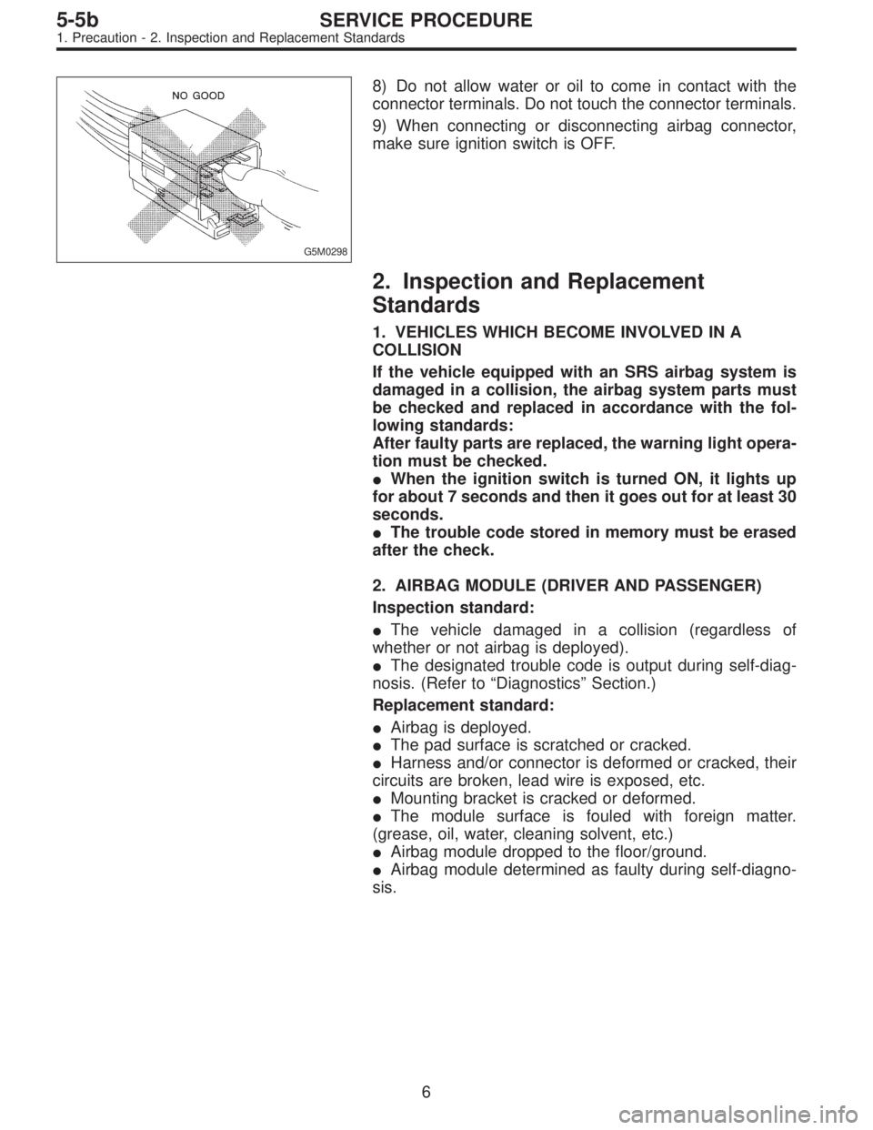
8) Do not allow water or oil to come in contact with the
connector terminals. Do not touch the connector terminals.
9) When connecting or disconnecting airbag connector,
make sure ignition switch is OFF.
2. Inspection and Replacement
Standards
1. VEHICLES WHICH BECOME INVOLVED IN A
COLLISION
If the vehicle equipped with an SRS airbag system is
damaged in a collision, the airbag system parts must
be checked and replaced in accordance with the fol-
lowing standards:
After faulty parts are replaced, the warning light opera-
tion must be checked.
�When the ignition switch is turned ON, it lights up
for about 7 seconds and then it goes out for at least 30
seconds.
�The trouble code stored in memory must be erased
after the check.
2. AIRBAG MODULE (DRIVER AND PASSENGER)
Inspection standard:
�The vehicle damaged in a collision (regardless of
whether or not airbag is deployed).
�The designated trouble code is output during self-diag-
nosis. (Refer to“Diagnostics”Section.)
Replacement standard:
�Airbag is deployed.
�The pad surface is scratched or cracked.
�Harness and/or connector is deformed or cracked, their
circuits are broken, lead wire is exposed, etc.
�Mounting bracket is cracked or deformed.
�The module surface is fouled with foreign matter.
(grease, oil, water, cleaning solvent, etc.)
�Airbag module dropped to the floor/ground.
�Airbag module determined as faulty during self-diagno-
sis.
6
5-5bSERVICE PROCEDURE
1. Precaution - 2. Inspection and Replacement Standards
Page 1685 of 3342
G5M0299
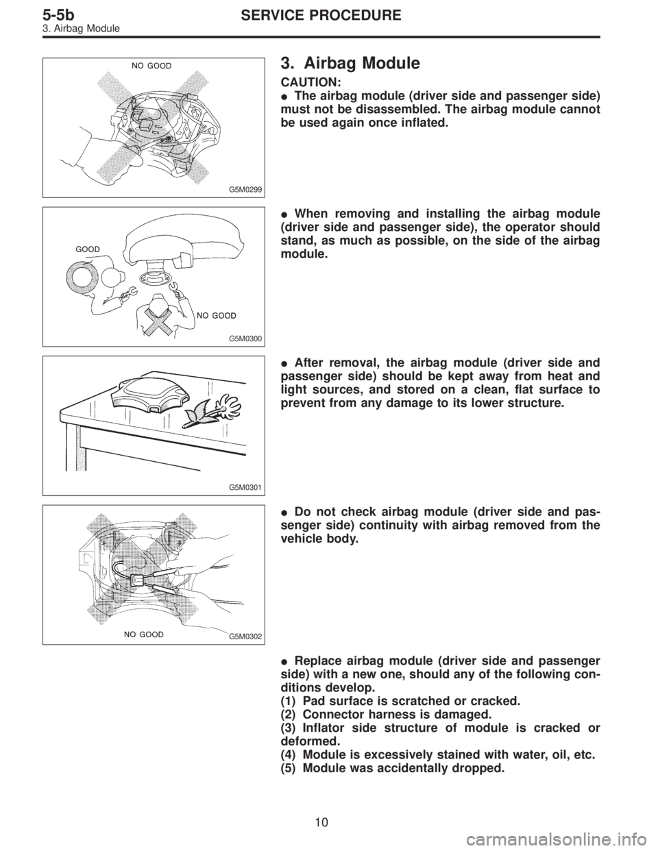
3. Airbag Module
CAUTION:
�The airbag module (driver side and passenger side)
must not be disassembled. The airbag module cannot
be used again once inflated.
G5M0300
�When removing and installing the airbag module
(driver side and passenger side), the operator should
stand, as much as possible, on the side of the airbag
module.
G5M0301
�After removal, the airbag module (driver side and
passenger side) should be kept away from heat and
light sources, and stored on a clean, flat surface to
prevent from any damage to its lower structure.
G5M0302
�Do not check airbag module (driver side and pas-
senger side) continuity with airbag removed from the
vehicle body.
�Replace airbag module (driver side and passenger
side) with a new one, should any of the following con-
ditions develop.
(1) Pad surface is scratched or cracked.
(2) Connector harness is damaged.
(3) Inflator side structure of module is cracked or
deformed.
(4) Module is excessively stained with water, oil, etc.
(5) Module was accidentally dropped.
10
5-5bSERVICE PROCEDURE
3. Airbag Module