Page 1265 of 3342
If the level is at lower point or below, add fluid to keep the
level in the specified range of the indicator. If at upper point
or above, drain fluid by using a syringe or the like.
Fluid capacity:
0.7�(0.7 US qt, 0.6 Imp qt)
B4M0563
(1) Check at temperature 21°C (70°F) on reservoir sur-
face of oil pump.
(2) Check at temperature 60°C (140°F) on reservoir
surface of oil pump.
81
4-3SERVICE PROCEDURE
9. Power Steering Fluid
Page 1269 of 3342
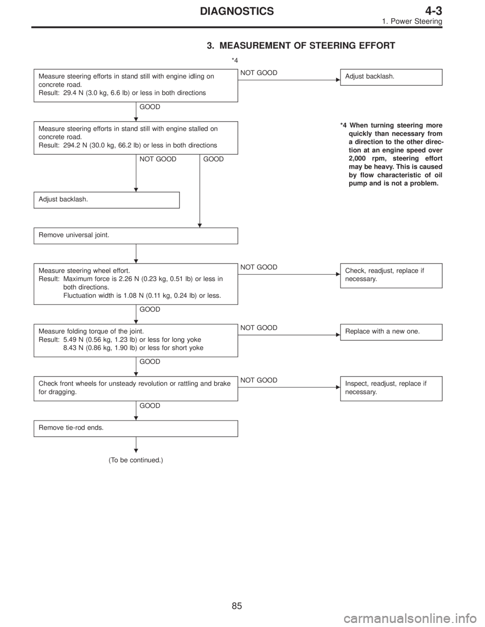
3. MEASUREMENT OF STEERING EFFORT
*4
Measure steering efforts in stand still with engine idling on
concrete road.
Result: 29.4 N (3.0 kg, 6.6 lb) or less in both directions
GOOD
�NOT GOOD
Adjust backlash.
Measure steering efforts in stand still with engine stalled on
concrete road.
Result: 294.2 N (30.0 kg, 66.2 lb) or less in both directions
NOT GOOD GOOD*4 When turning steering more
quickly than necessary from
a direction to the other direc-
tion at an engine speed over
2,000 rpm, steering effort
may be heavy. This is caused
by flow characteristic of oil
pump and is not a problem.
Adjust backlash.
Remove universal joint.
Measure steering wheel effort.
Result: Maximum force is 2.26 N (0.23 kg, 0.51 lb) or less in
both directions.
Fluctuation width is 1.08 N (0.11 kg, 0.24 lb) or less.
GOOD
�NOT GOOD
Check, readjust, replace if
necessary.
Measure folding torque of the joint.
Result: 5.49 N (0.56 kg, 1.23 lb) or less for long yoke
8.43 N (0.86 kg, 1.90 lb) or less for short yoke
GOOD
�NOT GOOD
Replace with a new one.
Check front wheels for unsteady revolution or rattling and brake
for dragging.
GOOD
�NOT GOOD
Inspect, readjust, replace if
necessary.
Remove tie-rod ends.
(To be continued.)
�
�
�
�
�
�
�
�
85
4-3DIAGNOSTICS
1. Power Steering
Page 1273 of 3342
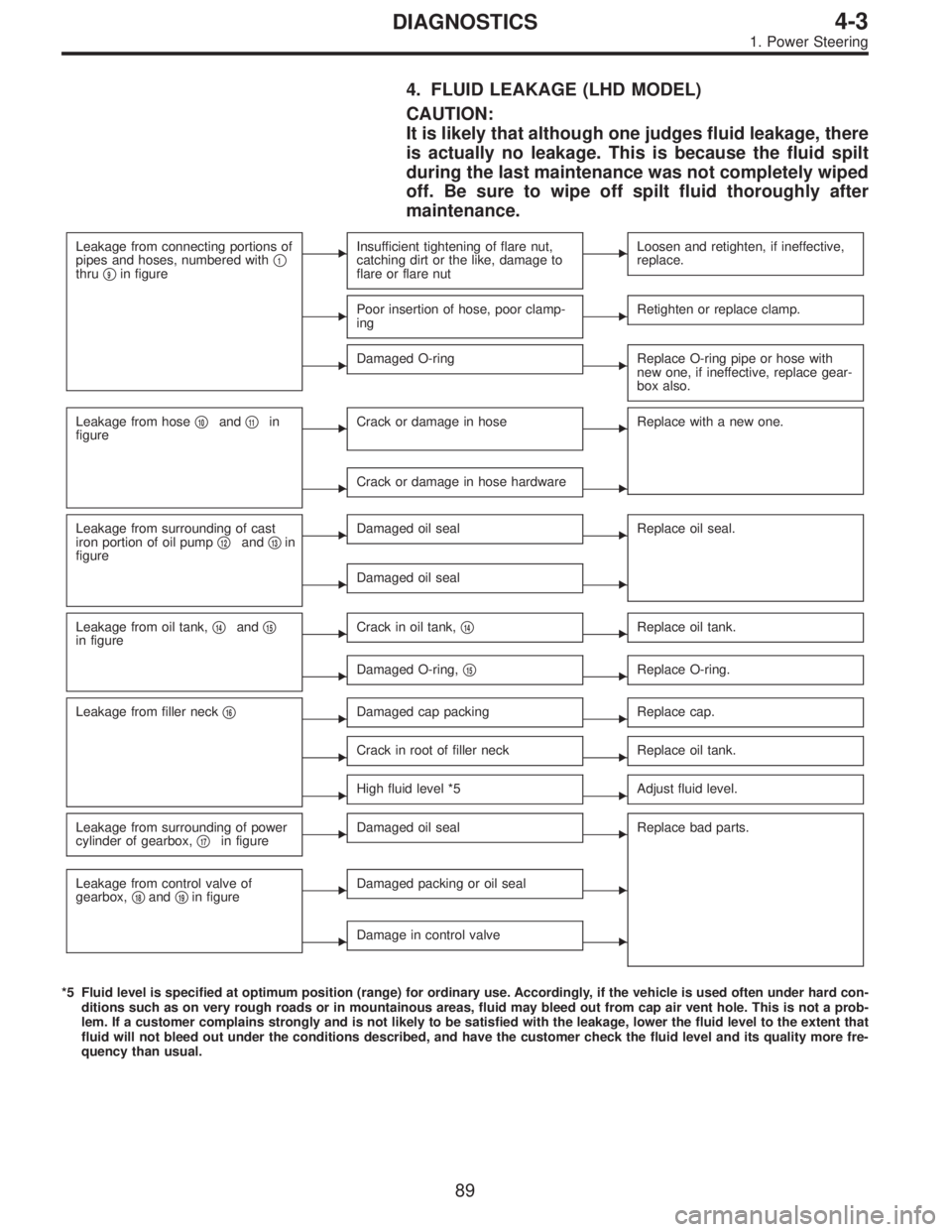
4. FLUID LEAKAGE (LHD MODEL)
CAUTION:
It is likely that although one judges fluid leakage, there
is actually no leakage. This is because the fluid spilt
during the last maintenance was not completely wiped
off. Be sure to wipe off spilt fluid thoroughly after
maintenance.
Leakage from connecting portions of
pipes and hoses, numbered with�1thru�9in figure
�Insufficient tightening of flare nut,
catching dirt or the like, damage to
flare or flare nut�Loosen and retighten, if ineffective,
replace.
�Poor insertion of hose, poor clamp-
ing�Retighten or replace clamp.
�Damaged O-ring�Replace O-ring pipe or hose with
new one, if ineffective, replace gear-
box also.
Leakage from hose�10and�11in
figure�Crack or damage in hose�Replace with a new one.
�Crack or damage in hose hardware�
Leakage from surrounding of cast
iron portion of oil pump�12and�13in
figure�Damaged oil seal�Replace oil seal.
�Damaged oil seal�
Leakage from oil tank,�14and�15in figure�Crack in oil tank,�14�Replace oil tank.
�Damaged O-ring,�15�Replace O-ring.
Leakage from filler neck�16�Damaged cap packing�Replace cap.
�Crack in root of filler neck�Replace oil tank.
�High fluid level *5�Adjust fluid level.
Leakage from surrounding of power
cylinder of gearbox,�17in figure�Damaged oil seal�Replace bad parts.
Leakage from control valve of
gearbox,�18and�19in figure�Damaged packing or oil seal�
�Damage in control valve�
*5 Fluid level is specified at optimum position (range) for ordinary use. Accordingly, if the vehicle is used often under hard con-
ditions such as on very rough roads or in mountainous areas, fluid may bleed out from cap air vent hole. This is not a prob-
lem. If a customer complains strongly and is not likely to be satisfied with the leakage, lower the fluid level to the extent that
fluid will not bleed out under the conditions described, and have the customer check the fluid level and its quality more fre-
quency than usual.
89
4-3DIAGNOSTICS
1. Power Steering
Page 1275 of 3342
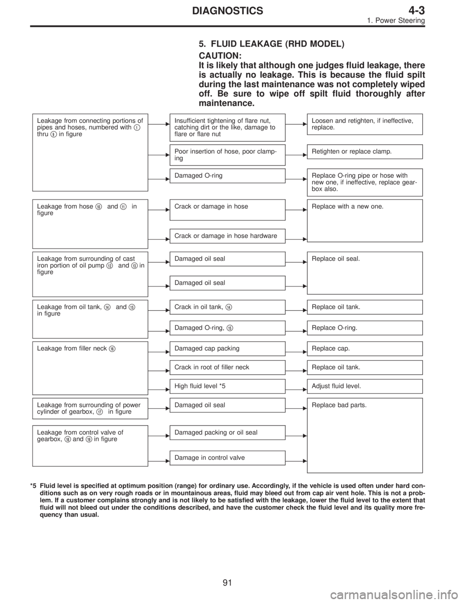
5. FLUID LEAKAGE (RHD MODEL)
CAUTION:
It is likely that although one judges fluid leakage, there
is actually no leakage. This is because the fluid spilt
during the last maintenance was not completely wiped
off. Be sure to wipe off spilt fluid thoroughly after
maintenance.
Leakage from connecting portions of
pipes and hoses, numbered with�1thru�9in figure
�Insufficient tightening of flare nut,
catching dirt or the like, damage to
flare or flare nut�Loosen and retighten, if ineffective,
replace.
�Poor insertion of hose, poor clamp-
ing�Retighten or replace clamp.
�Damaged O-ring�Replace O-ring pipe or hose with
new one, if ineffective, replace gear-
box also.
Leakage from hose�10and�11in
figure�Crack or damage in hose�Replace with a new one.
�Crack or damage in hose hardware�
Leakage from surrounding of cast
iron portion of oil pump�12and�13in
figure�Damaged oil seal�Replace oil seal.
�Damaged oil seal�
Leakage from oil tank,�14and�15in figure�Crack in oil tank,�14�Replace oil tank.
�Damaged O-ring,�15�Replace O-ring.
Leakage from filler neck�16�Damaged cap packing�Replace cap.
�Crack in root of filler neck�Replace oil tank.
�High fluid level *5�Adjust fluid level.
Leakage from surrounding of power
cylinder of gearbox,�17in figure�Damaged oil seal�Replace bad parts.
Leakage from control valve of
gearbox,�18and�19in figure�Damaged packing or oil seal�
�Damage in control valve�
*5 Fluid level is specified at optimum position (range) for ordinary use. Accordingly, if the vehicle is used often under hard con-
ditions such as on very rough roads or in mountainous areas, fluid may bleed out from cap air vent hole. This is not a prob-
lem. If a customer complains strongly and is not likely to be satisfied with the leakage, lower the fluid level to the extent that
fluid will not bleed out under the conditions described, and have the customer check the fluid level and its quality more fre-
quency than usual.
91
4-3DIAGNOSTICS
1. Power Steering
Page 1277 of 3342
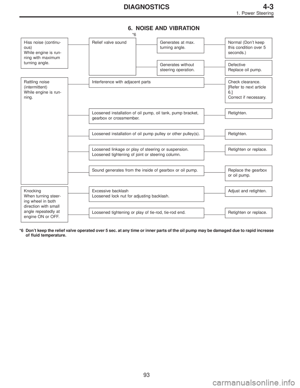
6. NOISE AND VIBRATION
*6
Hiss noise (continu-
ous)
While engine is run-
ning with maximum
turning angle.
Relief valve soundGenerates at max.
turning angle.Normal (Don’t keep
this condition over 5
seconds.)
Generates without
steering operation.Defective
Replace oil pump.
Rattling noise
(intermittent)
While engine is run-
ning.Interference with adjacent partsCheck clearance.
[Refer to next article
6.]
Correct if necessary.
Loosened installation of oil pump, oil tank, pump bracket,
gearbox or crossmember.Retighten.
Loosened installation of oil pump pulley or other pulley(s).Retighten.
Loosened linkage or play of steering or suspension.
Loosened tightening of joint or steering column.Retighten or replace.
Sound generates from the inside of gearbox or oil pump.Replace the gearbox
or oil pump.
Knocking
When turning steer-
ing wheel in both
direction with small
angle repeatedly at
engine ON or OFF.Excessive backlash
Loosened lock nut for adjusting backlash.Adjust and retighten.
Loosened tightening or play of tie-rod, tie-rod end.Retighten or replace.
*6 Don’t keep the relief valve operated over 5 sec. at any time or inner parts of the oil pump may be damaged due to rapid increase
of fluid temperature.
93
4-3DIAGNOSTICS
1. Power Steering
Page 1308 of 3342
B4M1167
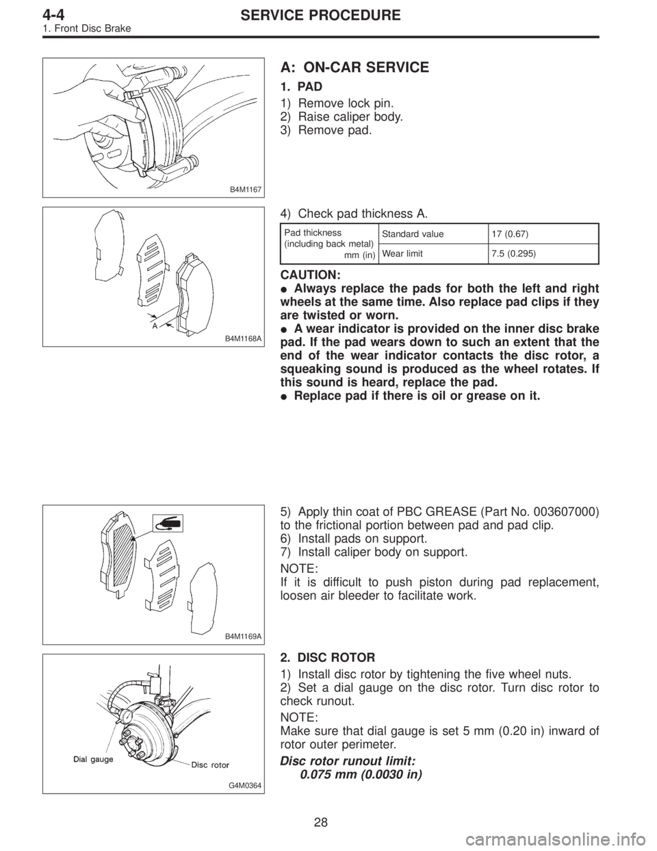
A: ON-CAR SERVICE
1. PAD
1) Remove lock pin.
2) Raise caliper body.
3) Remove pad.
B4M1168A
4) Check pad thickness A.
Pad thickness
(including back metal)
mm (in)Standard value 17 (0.67)
Wear limit 7.5 (0.295)
CAUTION:
�Always replace the pads for both the left and right
wheels at the same time. Also replace pad clips if they
are twisted or worn.
�A wear indicator is provided on the inner disc brake
pad. If the pad wears down to such an extent that the
end of the wear indicator contacts the disc rotor, a
squeaking sound is produced as the wheel rotates. If
this sound is heard, replace the pad.
�Replace pad if there is oil or grease on it.
B4M1169A
5) Apply thin coat of PBC GREASE (Part No. 003607000)
to the frictional portion between pad and pad clip.
6) Install pads on support.
7) Install caliper body on support.
NOTE:
If it is difficult to push piston during pad replacement,
loosen air bleeder to facilitate work.
G4M0364
2. DISC ROTOR
1) Install disc rotor by tightening the five wheel nuts.
2) Set a dial gauge on the disc rotor. Turn disc rotor to
check runout.
NOTE:
Make sure that dial gauge is set 5 mm (0.20 in) inward of
rotor outer perimeter.
Disc rotor runout limit:
0.075 mm (0.0030 in)
28
4-4SERVICE PROCEDURE
1. Front Disc Brake
Page 1318 of 3342
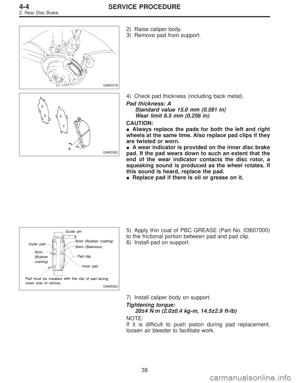
G4M0379
2) Raise caliper body.
3) Remove pad from support.
G4M0362
4) Check pad thickness (including back metal).
Pad thickness: A
Standard value 15.0 mm (0.591 in)
Wear limit 6.5 mm (0.256 in)
CAUTION:
�Always replace the pads for both the left and right
wheels at the same time. Also replace pad clips if they
are twisted or worn.
�A wear indicator is provided on the inner disc brake
pad. If the pad wears down to such an extent that the
end of the wear indicator contacts the disc rotor, a
squeaking sound is produced as the wheel rotates. If
this sound is heard, replace the pad.
�Replace pad if there is oil or grease on it.
G4M0363
5) Apply thin coat of PBC GREASE (Part No. 03607000)
to the frictional portion between pad and pad clip.
6) Install pad on support.
7) Install caliper body on support.
Tightening torque:
20±4 N⋅m (2.0±0.4 kg-m, 14.5±2.9 ft-lb)
NOTE:
If it is difficult to push piston during pad replacement,
loosen air bleeder to facilitate work.
38
4-4SERVICE PROCEDURE
2. Rear Disc Brake
Page 1353 of 3342
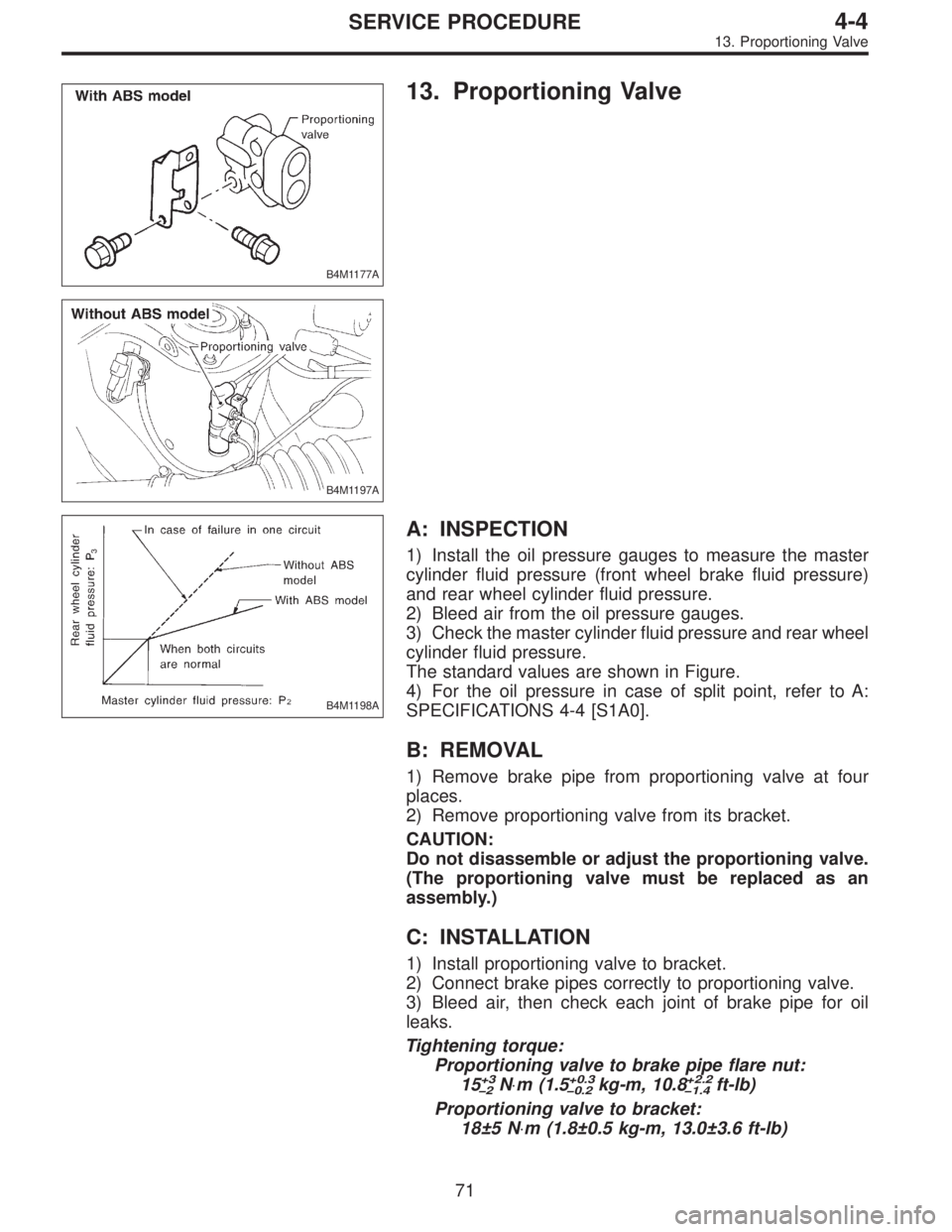
B4M1177A
13. Proportioning Valve
B4M1197A
B4M1198A
A: INSPECTION
1) Install the oil pressure gauges to measure the master
cylinder fluid pressure (front wheel brake fluid pressure)
and rear wheel cylinder fluid pressure.
2) Bleed air from the oil pressure gauges.
3) Check the master cylinder fluid pressure and rear wheel
cylinder fluid pressure.
The standard values are shown in Figure.
4) For the oil pressure in case of split point, refer to A:
SPECIFICATIONS 4-4 [S1A0].
B: REMOVAL
1) Remove brake pipe from proportioning valve at four
places.
2) Remove proportioning valve from its bracket.
CAUTION:
Do not disassemble or adjust the proportioning valve.
(The proportioning valve must be replaced as an
assembly.)
C: INSTALLATION
1) Install proportioning valve to bracket.
2) Connect brake pipes correctly to proportioning valve.
3) Bleed air, then check each joint of brake pipe for oil
leaks.
Tightening torque:
Proportioning valve to brake pipe flare nut:
15
+3
�2N⋅m (1.5+0.3
�0.2kg-m, 10.8+2.2
�1.4ft-lb)
Proportioning valve to bracket:
18±5 N⋅m (1.8±0.5 kg-m, 13.0±3.6 ft-lb)
71
4-4SERVICE PROCEDURE
13. Proportioning Valve