Page 1104 of 3342
G4M0511
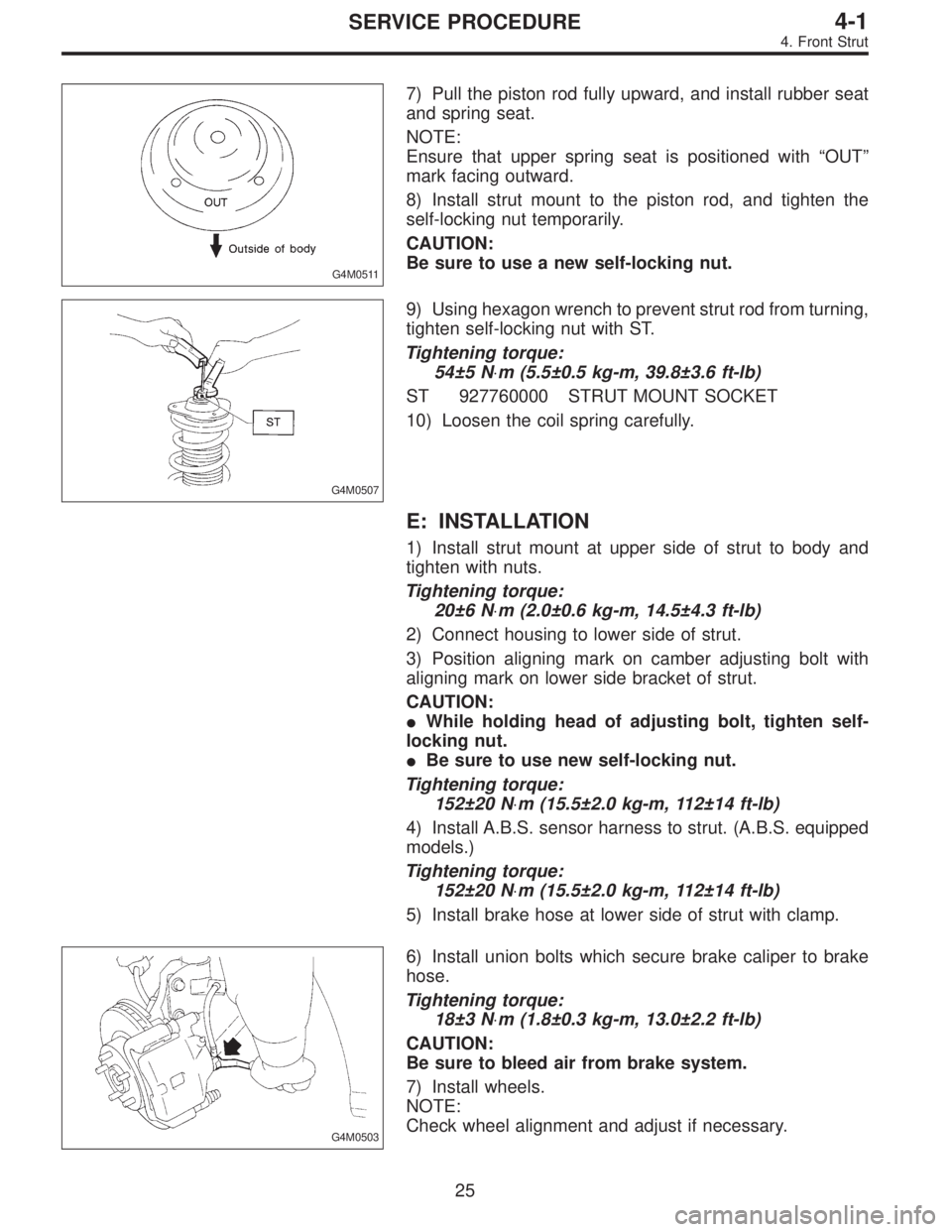
7) Pull the piston rod fully upward, and install rubber seat
and spring seat.
NOTE:
Ensure that upper spring seat is positioned with“OUT”
mark facing outward.
8) Install strut mount to the piston rod, and tighten the
self-locking nut temporarily.
CAUTION:
Be sure to use a new self-locking nut.
G4M0507
9) Using hexagon wrench to prevent strut rod from turning,
tighten self-locking nut with ST.
Tightening torque:
54±5 N⋅m (5.5±0.5 kg-m, 39.8±3.6 ft-lb)
ST 927760000 STRUT MOUNT SOCKET
10) Loosen the coil spring carefully.
E: INSTALLATION
1) Install strut mount at upper side of strut to body and
tighten with nuts.
Tightening torque:
20±6 N⋅m (2.0±0.6 kg-m, 14.5±4.3 ft-lb)
2) Connect housing to lower side of strut.
3) Position aligning mark on camber adjusting bolt with
aligning mark on lower side bracket of strut.
CAUTION:
�While holding head of adjusting bolt, tighten self-
locking nut.
�Be sure to use new self-locking nut.
Tightening torque:
152±20 N⋅m (15.5±2.0 kg-m, 112±14 ft-lb)
4) Install A.B.S. sensor harness to strut. (A.B.S. equipped
models.)
Tightening torque:
152±20 N⋅m (15.5±2.0 kg-m, 112±14 ft-lb)
5) Install brake hose at lower side of strut with clamp.
G4M0503
6) Install union bolts which secure brake caliper to brake
hose.
Tightening torque:
18±3 N⋅m (1.8±0.3 kg-m, 13.0±2.2 ft-lb)
CAUTION:
Be sure to bleed air from brake system.
7) Install wheels.
NOTE:
Check wheel alignment and adjust if necessary.
25
4-1SERVICE PROCEDURE
4. Front Strut
Page 1137 of 3342
H4M1001
5) Using flat bladed screwdriver, remove snap ring.
G4M0227
6) Using ST1, support housing securely.
7) Using ST2, press inner race to drive out outer bearing.
ST1 927400000 HOUSING STAND
ST2 927100000 BEARING REMOVER
CAUTION:
�Do not remove outer race unless it is faulty.
�Discard outer race after removal.
�Do not replace inner or outer race separately;
always replace as a unit.
8) Loosen bolts which secure tone wheel to hub. Remove
tone wheel (only vehicle equipped with A.B.S.).
G4M0228
9) Using ST and a hydraulic press, drive hub bolts out.
ST 927080000 HUB STAND
CAUTION:
Be careful not to hammer hub bolts. This may deform
hub.
H4M1002A
C: INSPECTION
Check the removed parts for wear and damage. If
defective, replace with new ones.
CAUTION:
�If bearing is faulty, replace it as a bearing set.
�Be sure to replace oil seal at every overhaul.
12
4-2SERVICE PROCEDURE
1. Front Axle
Page 1145 of 3342
G4M0250
B: DISASSEMBLY
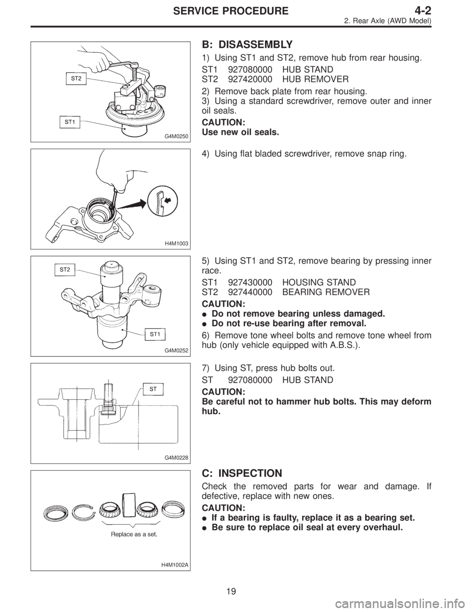
1) Using ST1 and ST2, remove hub from rear housing.
ST1 927080000 HUB STAND
ST2 927420000 HUB REMOVER
2) Remove back plate from rear housing.
3) Using a standard screwdriver, remove outer and inner
oil seals.
CAUTION:
Use new oil seals.
H4M1003
4) Using flat bladed screwdriver, remove snap ring.
G4M0252
5) Using ST1 and ST2, remove bearing by pressing inner
race.
ST1 927430000 HOUSING STAND
ST2 927440000 BEARING REMOVER
CAUTION:
�Do not remove bearing unless damaged.
�Do not re-use bearing after removal.
6) Remove tone wheel bolts and remove tone wheel from
hub (only vehicle equipped with A.B.S.).
G4M0228
7) Using ST, press hub bolts out.
ST 927080000 HUB STAND
CAUTION:
Be careful not to hammer hub bolts. This may deform
hub.
H4M1002A
C: INSPECTION
Check the removed parts for wear and damage. If
defective, replace with new ones.
CAUTION:
�If a bearing is faulty, replace it as a bearing set.
�Be sure to replace oil seal at every overhaul.
19
4-2SERVICE PROCEDURE
2. Rear Axle (AWD Model)
Page 1153 of 3342
G4M0276
2) Remove back plate from rear spindle.
G4M0277
3) Using ST, press hub bolts out.
CAUTION:
Do not hammer hub bolt since this may deform hub.
ST 927080000 HUB STAND
C: INSPECTION
Clean the removed parts and check them for wear, dam-
age and corrosion. If faulty, replace.
CAUTION:
Hub unit cannot be disassembled. If faulty, replace it
as a unit.
G4M0278
D: ASSEMBLY
1) Using ST, press new hub bolts into place.
NOTE:
�Use a 12 mm (0.47 in) hole in ST to prevent hub bolt
from tilting during installation.
�Ensure hub bolt closely contacts hub.
ST 927080000 HUB STAND
2) Completely clean dust or dirt from the mating/polished
surface of rear spindle back plate.
3) Install back plate to rear spindle.
Tightening torque:
52±6 N⋅m (5.3±0.6 kg-m, 38.3±4.3 ft-lb)
4) Charge oil seal located on the rear of hub with grease.
Specified grease:
SHELL 6459N
26
4-2SERVICE PROCEDURE
3. Rear Axle (FWD Model)
Page 1180 of 3342
B4M0053A
10. Wheel Balancing
1) Proper wheel balance may be lost if the tire is repaired
or if it wears. Check the tire for dynamic balance, and repair
as necessary.
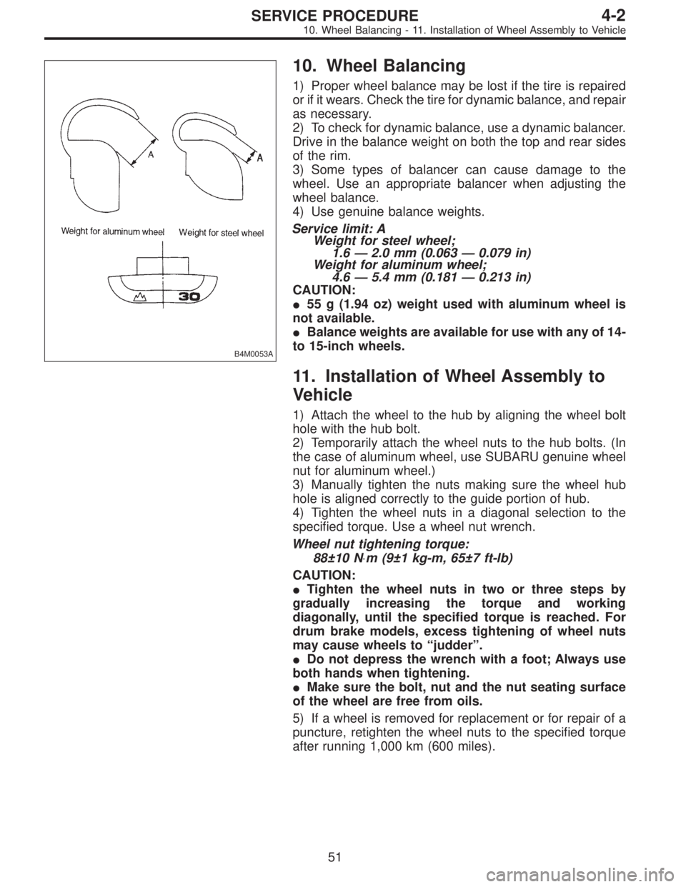
2) To check for dynamic balance, use a dynamic balancer.
Drive in the balance weight on both the top and rear sides
of the rim.
3) Some types of balancer can cause damage to the
wheel. Use an appropriate balancer when adjusting the
wheel balance.
4) Use genuine balance weights.
Service limit: A
Weight for steel wheel;
1.6—2.0 mm (0.063—0.079 in)
Weight for aluminum wheel;
4.6—5.4 mm (0.181—0.213 in)
CAUTION:
�55 g (1.94 oz) weight used with aluminum wheel is
not available.
�Balance weights are available for use with any of 14-
to 15-inch wheels.
11. Installation of Wheel Assembly to
Vehicle
1) Attach the wheel to the hub by aligning the wheel bolt
hole with the hub bolt.
2) Temporarily attach the wheel nuts to the hub bolts. (In
the case of aluminum wheel, use SUBARU genuine wheel
nut for aluminum wheel.)
3) Manually tighten the nuts making sure the wheel hub
hole is aligned correctly to the guide portion of hub.
4) Tighten the wheel nuts in a diagonal selection to the
specified torque. Use a wheel nut wrench.
Wheel nut tightening torque:
88±10 N⋅m (9±1 kg-m, 65±7 ft-lb)
CAUTION:
�Tighten the wheel nuts in two or three steps by
gradually increasing the torque and working
diagonally, until the specified torque is reached. For
drum brake models, excess tightening of wheel nuts
may cause wheels to “judder”.
�Do not depress the wrench with a foot; Always use
both hands when tightening.
�Make sure the bolt, nut and the nut seating surface
of the wheel are free from oils.
5) If a wheel is removed for replacement or for repair of a
puncture, retighten the wheel nuts to the specified torque
after running 1,000 km (600 miles).
51
4-2SERVICE PROCEDURE
10. Wheel Balancing - 11. Installation of Wheel Assembly to Vehicle
Page 1181 of 3342
B4M0053A
10. Wheel Balancing
1) Proper wheel balance may be lost if the tire is repaired
or if it wears. Check the tire for dynamic balance, and repair
as necessary.
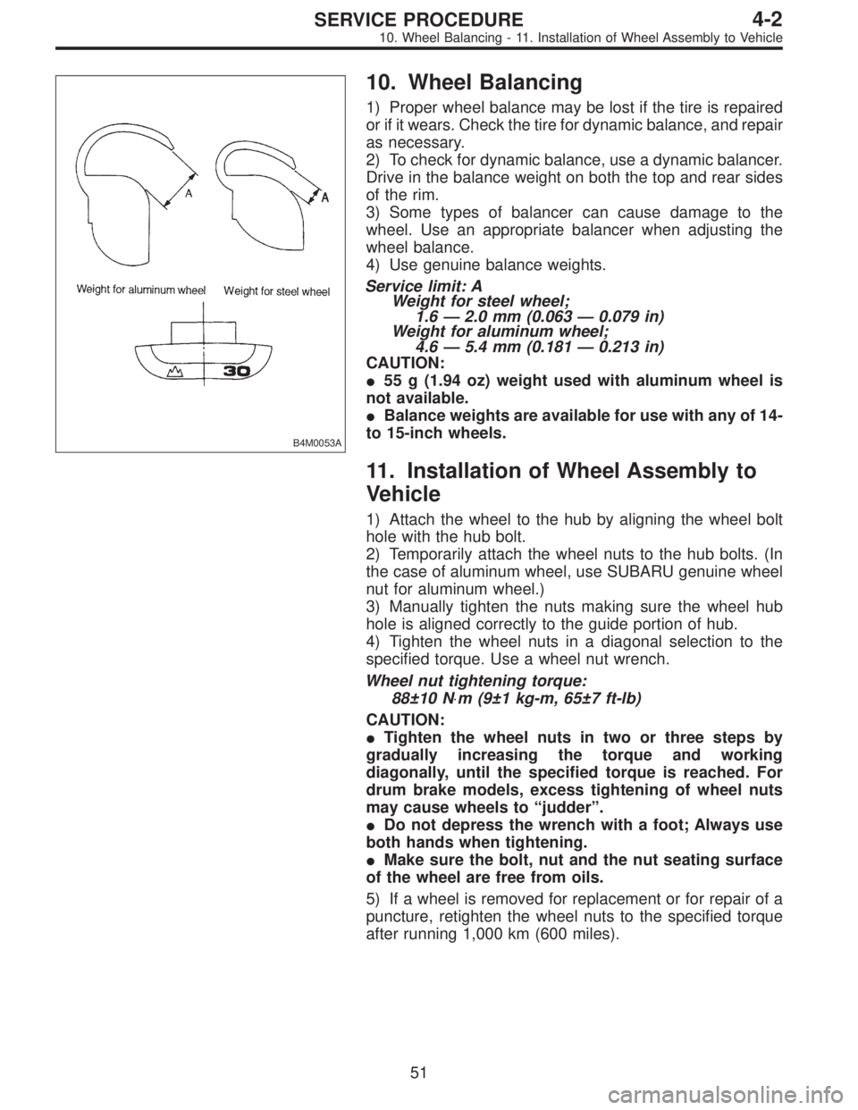
2) To check for dynamic balance, use a dynamic balancer.
Drive in the balance weight on both the top and rear sides
of the rim.
3) Some types of balancer can cause damage to the
wheel. Use an appropriate balancer when adjusting the
wheel balance.
4) Use genuine balance weights.
Service limit: A
Weight for steel wheel;
1.6—2.0 mm (0.063—0.079 in)
Weight for aluminum wheel;
4.6—5.4 mm (0.181—0.213 in)
CAUTION:
�55 g (1.94 oz) weight used with aluminum wheel is
not available.
�Balance weights are available for use with any of 14-
to 15-inch wheels.
11. Installation of Wheel Assembly to
Vehicle
1) Attach the wheel to the hub by aligning the wheel bolt
hole with the hub bolt.
2) Temporarily attach the wheel nuts to the hub bolts. (In
the case of aluminum wheel, use SUBARU genuine wheel
nut for aluminum wheel.)
3) Manually tighten the nuts making sure the wheel hub
hole is aligned correctly to the guide portion of hub.
4) Tighten the wheel nuts in a diagonal selection to the
specified torque. Use a wheel nut wrench.
Wheel nut tightening torque:
88±10 N⋅m (9±1 kg-m, 65±7 ft-lb)
CAUTION:
�Tighten the wheel nuts in two or three steps by
gradually increasing the torque and working
diagonally, until the specified torque is reached. For
drum brake models, excess tightening of wheel nuts
may cause wheels to “judder”.
�Do not depress the wrench with a foot; Always use
both hands when tightening.
�Make sure the bolt, nut and the nut seating surface
of the wheel are free from oils.
5) If a wheel is removed for replacement or for repair of a
puncture, retighten the wheel nuts to the specified torque
after running 1,000 km (600 miles).
51
4-2SERVICE PROCEDURE
10. Wheel Balancing - 11. Installation of Wheel Assembly to Vehicle
Page 1210 of 3342
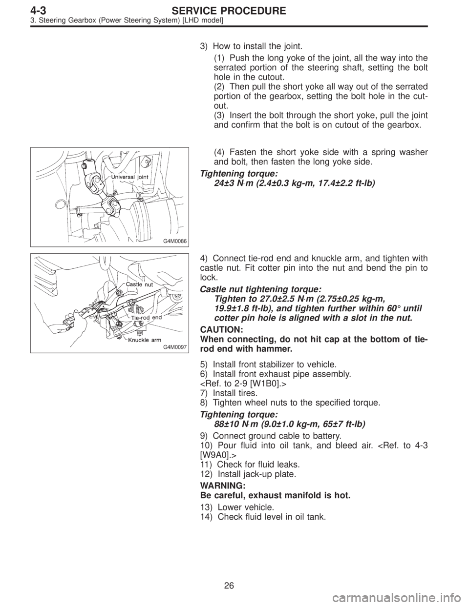
3) How to install the joint.
(1) Push the long yoke of the joint, all the way into the
serrated portion of the steering shaft, setting the bolt
hole in the cutout.
(2) Then pull the short yoke all way out of the serrated
portion of the gearbox, setting the bolt hole in the cut-
out.
(3) Insert the bolt through the short yoke, pull the joint
and confirm that the bolt is on cutout of the gearbox.
G4M0086
(4) Fasten the short yoke side with a spring washer
and bolt, then fasten the long yoke side.
Tightening torque:
24±3 N⋅m (2.4±0.3 kg-m, 17.4±2.2 ft-lb)
G4M0097
4) Connect tie-rod end and knuckle arm, and tighten with
castle nut. Fit cotter pin into the nut and bend the pin to
lock.
Castle nut tightening torque:
Tighten to 27.0±2.5 N⋅m (2.75±0.25 kg-m,
19.9±1.8 ft-lb), and tighten further within 60°until
cotter pin hole is aligned with a slot in the nut.
CAUTION:
When connecting, do not hit cap at the bottom of tie-
rod end with hammer.
5) Install front stabilizer to vehicle.
6) Install front exhaust pipe assembly.
7) Install tires.
8) Tighten wheel nuts to the specified torque.
Tightening torque:
88±10 N⋅m (9.0±1.0 kg-m, 65±7 ft-lb)
9) Connect ground cable to battery.
10) Pour fluid into oil tank, and bleed air.
[W9A0].>
11) Check for fluid leaks.
12) Install jack-up plate.
WARNING:
Be careful, exhaust manifold is hot.
13) Lower vehicle.
14) Check fluid level in oil tank.
26
4-3SERVICE PROCEDURE
3. Steering Gearbox (Power Steering System) [LHD model]
Page 1224 of 3342
![SUBARU LEGACY 1997 Service Repair Manual 5. Control Valve (Power Steering
Gearbox) [LHD model]
NOTE:
This section focuses on the disassembly and reassembly
of control valve. For the inspection and adjustment and the
service procedures for as SUBARU LEGACY 1997 Service Repair Manual 5. Control Valve (Power Steering
Gearbox) [LHD model]
NOTE:
This section focuses on the disassembly and reassembly
of control valve. For the inspection and adjustment and the
service procedures for as](/manual-img/17/57434/w960_57434-1223.png)
5. Control Valve (Power Steering
Gearbox) [LHD model]
NOTE:
This section focuses on the disassembly and reassembly
of control valve. For the inspection and adjustment and the
service procedures for associated parts, refer to“Steering
Gearbox”.
G4M0136
�1Power cylinder
�
2Cylinder
�
3Rack piston
�
4Rack axle
�
5Input shaft�
6Torsion bar
�
7Valve housing
�
8Valve body
�
9Control valve�
10Pipe B
�
11Pipe A
�
12Pinion
�
13Pinion axle
A: CHECKING OIL LEAKING POINTS
1. OIL LEAKING POINTS
1) If leak point is other than a, b, c, or d, perform check
step 5) in 4-3 [W5A2] before dismounting gearbox from
vehicle. If gearbox is dismounted without confirming where
the leak is, it must be mounted again to locate the leak
point.
2) Even if the location of the leak can be easily found by
observing the leaking condition, it is necessary to thor-
oughly remove the oil from the suspected portion and turn
the steering wheel from lock to lock about 30 to 40 times
with engine running, then make comparison of the sus-
pected portion between immediately after and several
hours after this operation.
3) Before starting oil leak repair work, be sure to clean the
gearbox, hoses, pipes, and surrounding parts. After com-
pleting repair work, clean these areas again.
40
4-3SERVICE PROCEDURE
5. Control Valve (Power Steering Gearbox) [LHD model]