Page 839 of 3342
G3M0950
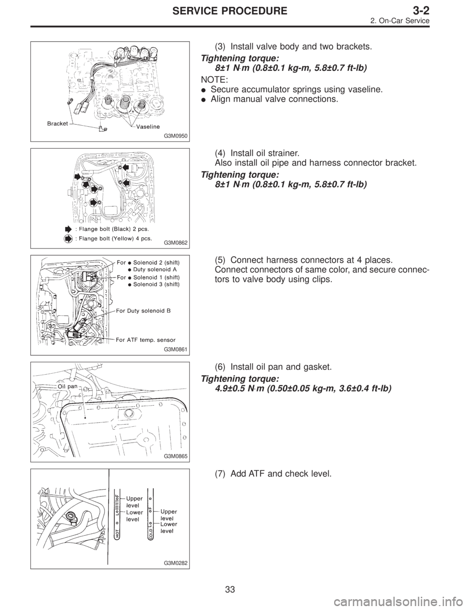
(3) Install valve body and two brackets.
Tightening torque:
8±1 N⋅m (0.8±0.1 kg-m, 5.8±0.7 ft-lb)
NOTE:
�Secure accumulator springs using vaseline.
�Align manual valve connections.
G3M0862
(4) Install oil strainer.
Also install oil pipe and harness connector bracket.
Tightening torque:
8±1 N⋅m (0.8±0.1 kg-m, 5.8±0.7 ft-lb)
G3M0861
(5) Connect harness connectors at 4 places.
Connect connectors of same color, and secure connec-
tors to valve body using clips.
G3M0865
(6) Install oil pan and gasket.
Tightening torque:
4.9±0.5 N⋅m (0.50±0.05 kg-m, 3.6±0.4 ft-lb)
G3M0282
(7) Add ATF and check level.
33
3-2SERVICE PROCEDURE
2. On-Car Service
Page 843 of 3342
G3M0782
(5) Install propeller shaft.
Tightening torque:
At rear differential
23±5 N⋅m (2.3±0.5 kg-m, 16.6±3.6 ft-lb)
At center bearing
39±5 N⋅m (4.0±0.5 kg-m, 28.9±3.6 ft-lb)
NOTE:
Align matching marks on propeller shaft and rear differen-
tial coupling.
G3M0305
(6) Install front exhaust pipe
Tightening torque:
At engine
29±5 N⋅m (3.0±0.5 kg-m, 21.7±3.6 ft-lb)
At hanger
29±5 N⋅m (3.0±0.5 kg-m, 21.7±3.6 ft-lb)
At front and rear connections
18±5 N⋅m (1.8±0.5 kg-m, 13.0±3.6 ft-lb)
G3M0313
(7) Lower and remove jack.
(8) Connect the following parts:
�Oxygen sensor connector
�Multi-connector
G3M0304
(9) Install pitching stopper.
Tightening torque:
Body side
57±10 N⋅m (5.8±1.0 kg-m, 42±7 ft-lb)
Engine side
49±5 N⋅m (5.0±0.5 kg-m, 36.2±3.6 ft-lb)
G3M0282
(10) Replenish ATF and check oil level. Check for
leaks.
37
3-2SERVICE PROCEDURE
2. On-Car Service
Page 844 of 3342

3. Performance Test
A: STALL TEST
1. GENERAL
The stall test is of extreme importance in diagnosing the
condition of the automatic transmission and the engine. It
should be conducted to measure the engine stall speeds in
all shift ranges except the P and N ranges.
Purposes of the stall test:
1) To check the operation of the automatic transmission
clutch.
2) To check the operation of the torque converter clutch.
3) To check engine performance.
2. TEST METHODS
Preparations before test:
�
1Check that throttle valve opens fully.
�
2Check that engine oil level is correct.
�
3Check that coolant level is correct.
�
4Check that ATF level is correct.
�
5Check that differential gear oil level is correct.
�
6Increase ATF temperature to 50 to 80°C (122 to 176°F)
by idling the engine for approximately 30 minutes (with
select lever set to“N”or“P”).
1) Install an engine tachometer at a location visible from
the driver’s compartment and mark the stall speed range
on the tachometer scale.
2) Place the wheel chocks at the front and rear of all
wheels and engage the parking brake.
3) Move the manual linkage to ensure it operates properly,
and shift the select lever to the 2 range.
B3M0286B
4) While forcibly depressing the foot brake pedal, gradu-
ally depress the accelerator pedal until the engine operates
at full throttle.
5) When the engine speed is stabilized, read that speed
quickly and release the accelerator pedal.
6) Shift the select lever to Neutral, and cool down the
engine by idling it for more than one minute.
7) Record the stall speed.
8) If stall speed in 2 range is higher than specifications,
forward clutch slipping on brake band slipping may occur.
To identify it, conduct the same test as above in D range.
9) Perform the stall tests with the select lever in the R
range.
CAUTION:
�Do not continue the stall test for MORE THAN FIVE
SECONDS at a time (from closed throttle, fully open
throttle to stall speed reading). Failure to follow this
instruction causes the engine oil and ATF to deterio-
rate and the clutch and brake band to be adversely
affected.
38
3-2SERVICE PROCEDURE
3. Performance Test
Page 847 of 3342

C: LINE PRESSURE TEST
1. GENERAL
If the clutch or the brake band shows a sign of slippage or
shifting sensation is not correct, the line pressure should be
checked.
�Excessive shocks during upshifting or shifting takes
place at a higher point than under normal circumstances,
may be due to the line pressure being too high.
�Slippage or inability to operate the vehicle may, in most
cases, be due to loss of oil pressure for the operation of
the clutch, brake band or control valve.
G3M0869
1) Line pressure measurement (under no load)
CAUTION:
�Before measuring line pressure, jack-up front
wheels (front-wheel-drive model) or all wheels (4-wheel
drive model).
�Maintain temperature of ATF at approximately 50°C
(122°F) during measurement.
(ATF will reach the above temperature after idling the
engine for approximately 30 minutes with select lever
in“N”or“P”.)
G3M0869
2) Line pressure measurement (under heavy load)
CAUTION:
�Before measuring line pressure, apply both foot and
parking brakes with all wheels chocked (Same as for
“stall”test conditions).
�Measure line pressure when select lever is in“R”,
“2”with engine under stall conditions.
�Measure line pressure within 5 seconds after shift-
ing the select lever to each position. (If line pressure
needs to be measured again, allow the engine to idle
and then stop. Wait for at least one minute before mea-
surement.)
�Maintain the temperature of ATF at approximately
50°C (122°F) during measurement. (ATF will reach the
above temperature after idling the engine for approxi-
mately 30 minutes with the select lever in“N”or“P”.)
41
3-2SERVICE PROCEDURE
3. Performance Test
Page 848 of 3342
 Temporarily attach the ST to a suitable place in the
driver’s compartment, remove the blind plug located in
front of the toe board and pass the hose of the ST to the
engin")
G3M0317
2. TEST METHODS
1) Temporarily attach the ST to a suitable place in the
driver’s compartment, remove the blind plug located in
front of the toe board and pass the hose of the ST to the
engine compartment.
ST 498575400 OIL PRESSURE GAUGE ASSY
�
1Pressure gauge hose
�
2Hole in toe board (blank cap hole)
�
3Brake pedal
G3M0869
2) Remove the test plug and install ST1 instead.
3) Connect ST1 with ST2.
ST1 498897200 OIL PRESSURE GAUGE ADAPTER
ST2 498575400 OIL PRESSURE GAUGE ASSY
4) Check for duty ratio changes by opening and closing
throttle valve using select monitor.
5) Check line pressure in accordance with the following
chart.
3. EVALUATION
NOTE:
�Under no load:“D”
�Under full load:“R”,“2”
(With engine running at stall speed)
Unit: kPa (kg/cm2, psi)
Line pressure
Duty ratio (%)“2”range“R”range“D”range
2200 cc 2500 cc
51,147—1,344
(11.7—13.1, 166—195)1,275—1,569
(13.0—16.0, 185—228)—
22——765—902
(7.8—9.2, 111—131)
100——235—481
(2.4—4.9, 34—70)392—490
(4.0—5.0, 57—71)
42
3-2SERVICE PROCEDURE
3. Performance Test
Page 849 of 3342

G3M0870
D: TRANSFER CLUTCH PRESSURE TEST
Check transfer clutch pressure in accordance with the fol-
lowing chart in the same manner as with line pressure.
ST 499897700 OIL PRESSURE ADAPTER SET
ST 498575400 OIL PRESSURE GAUGE ASSY
AWD mode:“D”range
FWD mode:“P”range, engine speed 2000 rpm
CAUTION:
Before setting in FWD mode, install spare fuse on FWD
mode switch.
Unit: kPa (kg/cm2, psi)
Duty ratio
(%)AWD mode FWD mode
5667—804
(6.8—8.2, 97—117)667—804
(6.8—8.2, 97—117)
40137—226
(1.4—2.3, 20—33)—
950
(0, 0)—
If oil pressure is not produced or if it does not change in the
AWD mode, the duty solenoid C or transfer valve assem-
bly may be malfunctioning. If oil pressure is produced in the
FWD mode, the problem is similar to that in the AWD
mode.
E: ROAD TEST
1. GENERAL
Road tests should be conducted to properly diagnose the
condition of the automatic transmission.
CAUTION:
When performing test, do not exceed posted speed
limit.
2. CHECKING FOR SHIFT PATTERNS
Check“kick-down”.
D range: 1st
←
→2nd←
→3rd←
→4th
3 range: 1st←
→2nd←
→3rd←4th
2 range: 2nd←3rd←4th
1 range: 1st←2nd←3rd←4th
3. CHECK FOR ENGINE BRAKE OPERATION
Engine brake operation:
D range→4th gear
3 range→3rd gear
2 range→2nd gear
1 range→1st gear
43
3-2SERVICE PROCEDURE
3. Performance Test
Page 850 of 3342
4. CHECK FOR THE AWD FUNCTION
If“tight-corner braking”occurs when the steering wheel is
fully turned at low speed:
1) Determine the applicable trouble code and check the
corresponding duty solenoid C (transfer) for improper
operation.
2) If the solenoid is operating properly, check transfer
clutch pressure.
3) If oil pressure is normal but“tight-corner braking”
occurs:
Check the transfer control valve for sticking, and the trans-
fer clutch facing for wear.
44
3-2SERVICE PROCEDURE
3. Performance Test
Page 865 of 3342
 Check the appearance of each component and clean.
CAUTION:
Make sure each part is free of harmful cuts, damage
and other")
B: ASSEMBLY OF OVERALL TRANSMISSION
1. TORQUE CONVERTER CLUTCH CASE SECTION
1) Check the appearance of each component and clean.
CAUTION:
Make sure each part is free of harmful cuts, damage
and other faults.
G3M0377
2) Install the washer and snap ring to the speedometer
shaft with ST, and set the oil seal. Then force-fit the shaft
to the torque converter clutch case.
ST 499827000 PRESS
3) Install vehicle speed sensor 2.
CAUTION:
Use new vehicle speed sensor 2, if it has been
removed.
Tightening torque:
5.9±1.5 N⋅m (60±15 kg-cm, 52±13 in-lb)
G3M0378
4) Install the speedometer driven gear to the speedometer
shaft, and secure with a snap ring.
G3M0379
5) Force-fit the oil seal to the torque converter clutch case
with ST.
ST 398437700 DRIFT
G3M0380
6) Install the differential assembly to the case, paying spe-
cial attention not to damage the speedometer gears (drive
and driven) and the inside of the case (particularly, the dif-
ferential side retainer contact surface).
59
3-2SERVICE PROCEDURE
4. Overall Transmission
 Install propeller shaft.
Tightening torque:
At rear differential
23±5 N⋅m (2.3±0.5 kg-m, 16.6±3.6 ft-lb)
At center bearing
39±5 N⋅m (4.0±0.5 kg-m, 28.9±3.6 ft-lb)
NOTE:
Align mat")
 Determine the applicable trouble code and check the
corresponding duty solenoi")