Page 653 of 3342
B3M0043A
4) Remove reverse check sleeve�5.
Disassembly procedure is as follows:
(1) Using a standard screwdriver, remove snap ring�
A
(Inner-28).
NOTE:
Replace snap ring with a new one if deformed or weak-
ened.
(2) Remove reverse check plate�
B.
(3) Remove reverse check spring�
Cwith cam�D.
(4) Remove reverse return spring�
E.
(5) Remove reverse accent shaft�
F.
(6) Remove O-ring�
G.
NOTE:
�Reverse check sleeve assembly uses an O-ring which
should not be scratched.
�Be careful not to break adjustment shim placed between
reverse check sleeve assembly and case.
B3M0042A
5) Remove back-up light switch�7.
6) Remove oil guide�
9.
Tightening torque:
T1: 6.4±0.5 N⋅m (0.65±0.05 kg-m, 4.7±0.4 ft-lb)
T2: 10±1 N⋅m (1.0±0.1 kg-m, 7.2±0.7 ft-lb)
T3: 19.6±1.5 N⋅m (2.00±0.15 kg-m, 14.5±1.1 ft-lb)
T4: 25±2 N⋅m (2.5±0.2 kg-m, 18.1±1.4 ft-lb)
21
3-1SERVICE PROCEDURE
2. Transfer Case and Extension (AWD Model)
Page 658 of 3342
 Installation of shifter arm�1and selector arm�8
Install shifter arm into the partition from the front while
inserting selector arm into the opening in reverse check
sleeve. Pass shaft thro")
B3M0042A
2) Installation of shifter arm�1and selector arm�8
Install shifter arm into the partition from the front while
inserting selector arm into the opening in reverse check
sleeve. Pass shaft through hole in selector arm until its end
comes out of the rear of transfer case.
NOTE:
Apply a coat of gear oil to shifter arm. Also make sure oil
seal is positioned properly.
Tightening torque:
T1: 6.4±0.5 N⋅m (0.65±0.05 kg-m, 4.7±0.4 ft-lb)
T2: 10±1 N⋅m (1.0±0.1 kg-m, 7.2±0.7 ft-lb)
T3: 19.6±1.5 N⋅m (2.00±0.15 kg-m, 14.5±1.1 ft-lb)
T4: 25±2 N⋅m (2.5±0.2 kg-m, 18.1±1.4 ft-lb)
B3M0049A
3. COMBINATION OF TRANSFER CASE AND
EXTENSION ASSEMBLY
1) Install center differential�
1and transfer driven gear�2
into transfer case.
Tightening torque:
T: 37±3 N⋅m (3.8±0.3 kg-m, 27.5±2.2 ft-lb)
B3M0050A
2) Selection of thrust washer (52 x 61 x t)
(1) Measure height“W”between transfer case and ball
bearing on the transfer driven gear�
3.
26
3-1SERVICE PROCEDURE
2. Transfer Case and Extension (AWD Model)
Page 662 of 3342
3. Rear Case (FWD Model)
A: DISASSEMBLY
G3M0952
Tightening torque: N⋅m (kg-m, ft-lb)
T1: 6.4±0.5 (0.65±0.05, 4.7±0.4)
T2: 10±1 (1.0±0.1, 7.2±0.7)
T3: 25±2 (2.5±0.2, 18.1±1.4)
1) Remove rear case�1.
2) Remove plug�
2, spring�3and reverse check ball�4.
3) Remove neutral switch�
5.
4) Pull out shifter arm�
6.
5) Remove reverse check sleeve�
7.
NOTE:
The disassembly procedure is the same as for AWD model.
B3M0056A
6) Remove back-up light switch�8.
7) Remove oil seal�
9.
CAUTION:
Do not reuse oil seal.
30
3-1SERVICE PROCEDURE
3. Rear Case (FWD Model)
Page 663 of 3342
 Assembly of rear case is in the reverse order of disas-
sembly.
G3M0952
Tightening torque: N⋅m (kg-m, ft-lb)
T1: 6.4±0.5 (0.65±0.05, 4.7±0.4)
T2: 10±1 (1.0±0.1, 7.2±0.7)
T3: 25�")
B: ASSEMBLY
1) Assembly of rear case is in the reverse order of disas-
sembly.
G3M0952
Tightening torque: N⋅m (kg-m, ft-lb)
T1: 6.4±0.5 (0.65±0.05, 4.7±0.4)
T2: 10±1 (1.0±0.1, 7.2±0.7)
T3: 25±5 (2.5±0.5, 18.1±3.6)
2) Installation of shifter arm�6
Install shifter arm into the partition from the front while
inserting selector arm into the opening in reverse check
sleeve. Pass shaft through hole in selector arm until its end
comes out of the rear of transmission case assembly.
CAUTION:
Apply a coat of gear oil to shifter arm. Also make sure
oil seal is positioned properly.
3) Adjustment of neutral position
NOTE:
After assembling and installing rear case, adjust neutral
position.
(1) Shift gear into 3rd gear position.
(2) Shifter arm turns lightly toward the 1st/2nd gear
side but heavily toward the reverse gear side because
of the function of the return spring, until arm contacts
the stopper.
(3) Make adjustment so that the heavy stroke (reverse
side) is a little more than the light stroke (1st/2nd side).
(4) To adjust, remove bolts holding reverse check
sleeve assembly to the case, move sleeve assembly
outward, and place adjustment shim (0 to 1 ea.)
between sleeve assembly and case to adjust the clear-
ance.
31
3-1SERVICE PROCEDURE
3. Rear Case (FWD Model)
Page 672 of 3342
G3M0552
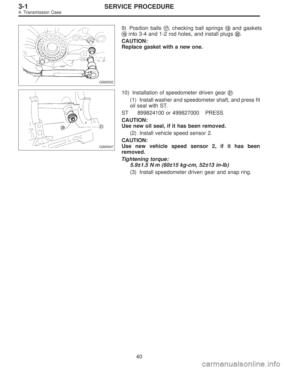
9) Position balls�17, checking ball springs�18and gaskets
�
19into 3-4 and 1-2 rod holes, and install plugs�20.
CAUTION:
Replace gasket with a new one.
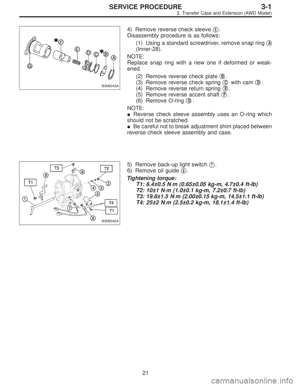
G3M0547
10) Installation of speedometer driven gear�21
(1) Install washer and speedometer shaft, and press fit
oil seal with ST.
ST 899824100 or 499827000 PRESS
CAUTION:
Use new oil seal, if it has been removed.
(2) Install vehicle speed sensor 2.
CAUTION:
Use new vehicle speed sensor 2, if it has been
removed.
Tightening torque:
5.9±1.5 N⋅m (60±15 kg-cm, 52±13 in-lb)
(3) Install speedometer driven gear and snap ring.
40
3-1SERVICE PROCEDURE
4. Transmission Case
Page 678 of 3342
 Place the transmission with case left side facing
downward and put ST1 on bearing cup.
(2) Screw retainer assembly into left case from the bot-
tom with ST2. Fit ST3 on the transmission ma")
G3M0564
(1) Place the transmission with case left side facing
downward and put ST1 on bearing cup.
(2) Screw retainer assembly into left case from the bot-
tom with ST2. Fit ST3 on the transmission main shaft.
Shift gear into 4th or 5th and turn the shaft several
times. Screw in the retainer while turning ST3 until a
slight resistance is felt on ST2.
This is the contact point of hypoid gear and drive pin-
ion shaft. Repeat the above sequence several times to
ensure the contact point.
ST1 399780104 WEIGHT
ST2 499787000 WRENCH ASSY
ST3 499927100 HANDLE
B3M0340A
(3) Remove weight and screw in retainer without
O-ring on the upper side and stop at the point where
slight resistance is felt.
NOTE:
At this point, the backlash between the hypoid gear and
drive pinion shaft is zero.
ST 499787000 WRENCH ASSY
B3M0334A
(4) Fit lock plate�11. Loosen the retainer on the lower
side by 1-1/2 notches of lock plate and turn in the
retainer on the upper side by the same amount in order
to obtain the backlash.
NOTE:
The notch on the lock plate moves by 1/2 notch if the plate
is turned upside down.
(5) Turn in the retainer on the upper side additionally
by 1 notch in order to apply preload on taper roller
bearing.
(6) Tighten temporarily both the upper and lower lock
plates and mark both holder and lock plate for later
readjustment.
(7) Turn transmission main shaft several times while
tapping around retainer lightly with plastic hammer.
(8) Set ST1 and ST2. Insert the needle through trans-
mission oil drain plug hole so that the needle comes in
contact with the tooth surface at a right angle and check
the backlash.
46
3-1SERVICE PROCEDURE
4. Transmission Case
Page 706 of 3342

1. Manual Transmission and
Differential
Symptom and possible cause Remedy
1. Gears are difficult to intermesh.
The cause for difficulty in shifting gears can be classified into two kinds: one is malfunction of the gear shift system and the
other is malfunction of the transmission. However, if the operation is heavy and engagement of the gears is difficult, defective
clutch disengagement may also be responsible. Check whether the clutch is correctly functioning, before checking the gear
shift system and transmission.
(a) Worn, damaged or burred chamfer of internal spline of
sleeve and reverse driven gearReplace.
(b) Worn, damaged or burred chamfer of spline of gears Replace.
(c) Worn or scratched bushings Replace.
(d) Incorrect contact between synchronizer ring and gear
cone or wearCorrect or replace.
2. Gear slips out.
(1) Gear slips out when coasting on rough road.
(2) Gear slips out during acceleration.
(a) Defective pitching stopper adjustment Adjust.
(b) Loose engine mounting bolts Tighten or replace.
(c) Worn fork shifter, broken shifter fork rail spring Replace.
(d) Worn or damaged ball bearing Replace.
(e) Excessive clearance between splines of synchronizer hub
and synchronizer sleeveReplace.
(f) Worn tooth step of synchronizer hub (responsible for slip-
out of 3rd gear)Replace.
(g) Worn 1st driven gear, needle bearing and race Replace.
(h) Worn 2nd driven gear, needle bearing and race Replace.
(i) Worn 3rd drive gear and bushing Replace.
(j) Worn 4th drive gear and bushing Replace.
(k) Worn reverse idler gear and bushing Replace.
3. Unusual noise comes from transmission.
If an unusual noise is heard when the vehicle is parked with its engine idling and if the noise ceases when the clutch is
disengaged, it may be considered that the noise comes from the transmission.
(a) Insufficient or improper lubrication Lubricate or replace with specified oil.
(b) Worn or damaged gears and bearings Replace.
NOTE: If the trouble is only wear of the tooth surfaces, merely
a high roaring noise will occur at high speeds, but if any part
is broken, rhythmical knocking sound will be heard even at
low speeds.
72
3-1DIAGNOSTICS
1. Manual Transmission and Differential
Page 707 of 3342

Abnormal noise will develop and finally it will become impossible to continue to run due to broken pieces obstructi")
Symptom and possible cause Remedy
4. Broken differential (case, gear, bearing, etc.)
Abnormal noise will develop and finally it will become impossible to continue to run due to broken pieces obstructing the gear
revolution.
(a) Insufficient or improper oil Disassemble differential and replace broken components and
at the same time check other components for any trouble,
and replace if necessary.
(b) Use of vehicle under severe conditions such as excessive
load and improper use of clutchReadjust bearing preload and backlash and face contact of
gears.
(c) Improper adjustment of taper roller bearing Adjust.
(d) Improper adjustment of drive pinion and hypoid driven
gearAdjust.
(e) Excessive backlash due to worn differential side gear,
washer or differential pinionAdd recommended oil to specified level. Do not use vehicle
under severe operating conditions.
(f) Loose hypoid driven gear clamping bolts Tighten.
5. Differential and hypoid gear noises
Troubles of the differential and hypoid gear always appear as noise problems. Therefore noise is the first indication of the
trouble. However noises from the engine, muffler, tire, exhaust gas, bearing, body, etc. are easily mistaken for the differential
noise. Pay special attention to the hypoid gear noise because it is easily confused with other gear noises. There are the
following four kinds of noises.
(1) Gear noise when driving: If noise increases as vehicle speed increases it may be due to insufficient gear oil, incorrect
gear engagement, damaged gears, etc.
(2) Gear noise when coasting: Damaged gears due to maladjusted bearings and incorrect shim adjustment
(3) Bearing noise when driving or when coasting: Cracked, broken or damaged bearings
(4) Noise which mainly occurs when turning: Unusual noise from differential side gear, differential pinion, differential pinion
shaft, etc.
(a) Insufficient oil Lubricate.
(b) Improper adjustment of hypoid driven gear and drive
pinionCheck tooth contact.
(c) Worn teeth of hypoid driven gear and drive pinion Replace as a set.
Readjust bearing preload.
(d) Loose roller bearing Readjust hypoid driven gear to drive pinion backlash and
check tooth contact.
(e) Distorted hypoid driven gear or differential case Replace.
(f) Worn washer and differential pinion shaft Replace.
73
3-1DIAGNOSTICS
1. Manual Transmission and Differential

A: DISASSEMBLY
G3M0952
Tightening torque: N⋅m (kg-m, ft-lb)
T1: 6.4±0.5 (0.65±0.05, 4.7±0.4)
T2: 10±1 (1.0±0.1, 7.2±0.7)
T3: 25±2 (2.5±0.2, 18.1±1.4)
1) Remove rear")