Page 381 of 3342
 If the clearance between valve guide and stem exceeds
the specification, replace guide as follows:
(1) Place cylinder head on ST1 with the combustion
chamber upward so that valve guides ent")
G2M0762
2) If the clearance between valve guide and stem exceeds
the specification, replace guide as follows:
(1) Place cylinder head on ST1 with the combustion
chamber upward so that valve guides enter the holes
in ST1.
(2) Insert ST2 into valve guide and press it down to
remove valve guide.
ST1 498267600 CYLINDER HEAD TABLE
ST2 499767200 VALVE GUIDE REMOVER
G2M0763
(3) Turn cylinder head upside down and place ST as
shown in the figure.
ST 498267700 VALVE GUIDE ADJUSTER
G2M0764
(4) Before installing new valve guide, make sure that
neither scratches nor damages exist on the inside sur-
face of the valve guide holes in cylinder head.
(5) Put new valve guide, coated with sufficient oil, in
cylinder, and insert ST1 into valve guide. Press in until
the valve guide upper end is flush with the upper sur-
face of ST2.
ST1 499767200 VALVE GUIDE REMOVER
ST2 498267700 VALVE GUIDE ADJUSTER
(6) Check the valve guide protrusion.
Valve guide protrusion: L
12.0—12.4 mm (0.472—0.488 in)
(7) Ream the inside of valve guide with ST. Gently
rotate the reamer clockwise while pressing it lightly into
valve guide, and return it also rotating clockwise. After
reaming, clean valve guide to remove chips.
ST 499767400 VALVE GUIDE REAMER
CAUTION:
�Apply engine oil to the reamer when reaming.
�If the inner surface of the valve guide is torn, the
edge of the reamer should be slightly ground with an
oil stone.
�If the inner surface of the valve guide becomes lus-
trous and the reamer does not chips, use a new reamer
or remedy the reamer.
(8) Recheck the contact condition between valve and
valve seat after replacing valve guide.
40
2-3bSERVICE PROCEDURE
4. Cylinder Head
Page 382 of 3342
 Inspect the flange and stem of valve, and replace if
damaged, worn, or deformed, or if“H”is less than the
specified limit.
H:
Intake
Standard
1.2 mm (0.047 i")
G2M0153
4. INTAKE AND EXHAUST VALVE
1) Inspect the flange and stem of valve, and replace if
damaged, worn, or deformed, or if“H”is less than the
specified limit.
H:
Intake
Standard
1.2 mm (0.047 in)
Limit
0.8 mm (0.031 in)
Exhaust
Standard
1.5 mm (0.059 in)
Limit
0.8 mm (0.031 in)
Valve overall length:
Intake 105.9 mm (4.169 in)
Exhaust 106.2 mm (4.181 in)
2) Put a small amount of grinding compound on the seat
surface and lap the valve and seat surface. Install a new
intake valve oil seal after lapping.
G2M0154
5. VALVE SPRINGS
1) Check valve springs for damage, free length, and ten-
sion. Replace valve spring if it is not to the specifications
presented below.
2) To measure the squareness of the valve spring, stand
the spring on a surface plate and measure its deflection at
the top using a try square.
Valve spring
Free length 48.04 mm (1.8913 in)
Tension/spring height146.1—167.7 N
(14.9—17.1 kg, 32.9—37.7 lb)/42.0 mm
(1.654 in)
455.0—523.7 N
(46.4—53.4 kg, 102.3—117.7 lb)/33.4 mm
(1.315 in)
Squareness 2.5°, 2.1 mm (0.083 in)
G2M0765
6. INTAKE AND EXHAUST VALVE OIL SEAL
Replace oil seal with new one, if lip is damaged or spring
out of place, or when the surfaces of intake valve and valve
seat are reconditioned or intake valve guide is replaced.
1) Place cylinder head on ST1.
2) Press in oil seal to the specified dimension indicated in
the figure by using ST2.
ST1 498267600 CYLINDER HEAD TABLE
ST2 498857100 VALVE OIL SEAL GUIDE
41
2-3bSERVICE PROCEDURE
4. Cylinder Head
Page 383 of 3342
CAUTION:
�Apply engine oil to oil seal before force-fitting.
�Differentiate between intake valve oil seal and
exhaust valve oil seal by noting their difference in
color.
Color of rubber part:
Intake [Black]
Exhaust [Brown]
Color of spring part:
Intake [Black]
Exhaust [Black]
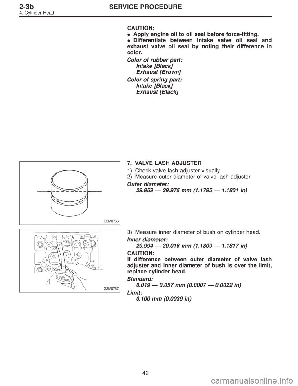
G2M0766
7. VALVE LASH ADJUSTER
1) Check valve lash adjuster visually.
2) Measure outer diameter of valve lash adjuster.
Outer diameter:
29.959—29.975 mm (1.1795—1.1801 in)
G2M0767
3) Measure inner diameter of bush on cylinder head.
Inner diameter:
29.994—30.016 mm (1.1809—1.1817 in)
CAUTION:
If difference between outer diameter of valve lash
adjuster and inner diameter of bush is over the limit,
replace cylinder head.
Standard:
0.019—0.057 mm (0.0007—0.0022 in)
Limit:
0.100 mm (0.0039 in)
42
2-3bSERVICE PROCEDURE
4. Cylinder Head
Page 399 of 3342
C: INSPECTION
1. CYLINDER BLOCK
1) Check for cracks and damage visually. Especially,
inspect important parts by means of red lead check.
2) Check the oil passages for clogging.
3) Inspect crankcase surface that mates with cylinder
head for warping by using a straight edge, and correct by
grinding if necessary.
Warping limit:
0.05 mm (0.0020 in)
Grinding limit:
0.1 mm (0.004 in)
Standard height of cylinder block:
201.0 mm (7.91 in)
B2M0082A
2. CYLINDER AND PISTON
1) The cylinder bore size is stamped on the cylinder
block’s front upper surface.
NOTE:
Standard sized pistons are classified into two grades,“A”
and“B”. These grades should be used as a guide line in
selecting a standard piston.
Standard diameter:
A: 99.505—99.515 mm (3.9175—3.9179 in)
B: 99.495—99.505 mm (3.9171—3.9175 in)
58
2-3bSERVICE PROCEDURE
5. Cylinder Block
Page 402 of 3342
 Check circlip installation groove on the piston for burr.
If necessary, remove burr from the groove so that piston
pin can lightly move.
5) Check piston pin circlip for distortion")
B2M0084A
B2M0420A
4) Check circlip installation groove on the piston for burr.
If necessary, remove burr from the groove so that piston
pin can lightly move.
5) Check piston pin circlip for distortion, cracks and wear.
G2M0172
4. PISTON RING
1) If piston ring is broken, damaged, or worn, or if its ten-
sion is insufficient, or when the piston is replaced, replace
piston ring with a new one of the same size as the piston.
CAUTION:
�“R”or“N”is marked on the end of the top and sec-
ond rings. When installing the rings to the piston, face
this mark upward.
G2M0624
�The oil ring is a combined ring consisting of two
rails and a spacer in between. When installing, be care-
ful to assemble correctly.
G2M0174
2) Squarely place piston ring and oil ring in cylinder, and
measure the piston ring gap with a thickness gauge.
Unit: mm (in)
Standard Limit
Piston
ring gapTop ring0.20—0.35
(0.0079—0.0138)1.0 (0.039)
Second ring0.37—0.52
(0.0146—0.0205)1.0 (0.039)
Oil ring rail0.20—0.60
(0.0079—0.0236)1.5 (0.059)
61
2-3bSERVICE PROCEDURE
5. Cylinder Block
Page 405 of 3342
B2M0085
6) Inspect bushing at connecting rod small end, and
replace if worn or damaged. Also measure the piston pin
clearance at the connecting rod small end.
Clearance between piston pin and bushing:
Standard
0—0.022 mm (0—0.0009 in)
Limit
0.030 mm (0.0012 in)
B2M0084A
G2M0177
7) Replacement procedure is as follows.
(1) Remove bushing from connecting rod with ST and
press.
(2) Press bushing with ST after applying oil on the
periphery of bushing.
ST 499037100 CONNECTING ROD BUSHING
REMOVER AND INSTALLER
(3) Make two 3 mm (0.12 in) holes in bushing. Ream
the inside of bushing.
(4) After completion of reaming, clean bushing to
remove chips.
6. CRANKSHAFT AND CRANKSHAFT BEARING
1) Clean crankshaft completely and check for cracks by
means of red lead check etc., and replace if defective.
64
2-3bSERVICE PROCEDURE
5. Cylinder Block
Page 408 of 3342
D: ASSEMBLY
1. CRANKSHAFT AND PISTON
B2M0127A
Tightening torque: N⋅m (kg-m, ft-lb)
T: 44±2 (4.5±0.2, 32.5±1.4)
1) Install connecting rod bearings on connecting rods and
connecting rod caps.
CAUTION:
Apply oil to the surfaces of the connecting rod bear-
ings.
2) Install connecting rod on crankshaft.
CAUTION:
Position each connecting rod with the side marked
facing forward.
3) Install connecting rod cap with connecting rod nut.
Ensure the arrow on connecting rod cap faces the front
during installation.
CAUTION:
�Each connecting rod has its own mating cap. Make
sure that they are assembled correctly by checking
their matching number.
�When tightening the connecting rod nuts, apply oil
on the threads.
67
2-3bSERVICE PROCEDURE
5. Cylinder Block
Page 421 of 3342

2. Engine Noise
Type of sound Condition Possible cause
Regular clicking soundSound increases as engine
speed increases.Valve mechanism is defective.
�Incorrect valve clearance
�Worn camshaft
�Broken valve spring
Heavy and dull clankOil pressure is low.�Worn crankshaft main bearing
�Worn connecting rod bearing (big end)
Oil pressure is normal.�Loose flywheel mounting bolts
�Damaged engine mounting
High-pitched clank
(Spark knock)Sound is noticeable when
accelerating with an overload.�Ignition timing advanced
�Accumulation of carbon inside combustion chamber
�Wrong spark plug
�Improper gasoline
Clank when engine speed is
medium (1,000 to 2,000 rpm).Sound is reduced when fuel
injector connector of noisy
cylinder is disconnected.
(NOTE*)�Worn crankshaft main bearing
�Worn bearing at crankshaft end of connecting rod
Knocking sound when engine
is operating under idling speed
and engine is warm.Sound is reduced when fuel
injector connector of noisy
cylinder is disconnected.
(NOTE*)�Worn cylinder liner and piston ring
�Broken or stuck piston ring
�Worn piston pin and hole at piston end of connecting rod
Sound is not reduced if each
fuel injector connector is
disconnected in turn. (NOTE*)�Unusually worn valve lifter
�Worn camshaft journal bore in crankcase
Squeaky sound—�Insufficient generator lubrication
Rubbing sound—�Defective generator brush and rotor contact
Gear scream when starting
engine—�Defective ignition starter switch
�Worn gear and starter pinion
Sound like polishing glass with
a dry cloth—�Loose drive belt
�Defective engine coolant pump shaft
Hissing sound—�Loss of compression
�Air leakage in air intake system, hoses, connections or
manifolds
Timing belt noise—�Loose timing belt
�Belt contacting case/adjacent part
Valve tappet noise—�Incorrect valve clearance
NOTE*:
When disconnecting fuel injector connector, Malfunction Indicator Light (CHECK ENGINE light) illuminates and trouble code is stored in
ECM memory.
Therefore, carry out the CLEAR MEMORY MODE and INSPECTION MODE after connecting fuel injector connector. (Ref. to 2-7 On-Board
Diagnostics II System.)
80
2-3bDIAGNOSTICS
2. Engine Noise
 Check for cracks and damage visually. Especially,
inspect important parts by means of red lead check.
2) Check the oil passages for clogging.
3) Inspect crankcase su")
 Inspect bushing at connecting rod small end, and
replace if worn or damaged. Also measure the piston pin
clearance at the connecting rod small end.
Clearance between piston pin and bushing:")

T: 44±2 (4.5±0.2, 32.5±1.4)
1) Install connecting rod bearings on connecting rods and
connecting rod caps.
CAUTI")