Page 296 of 3342
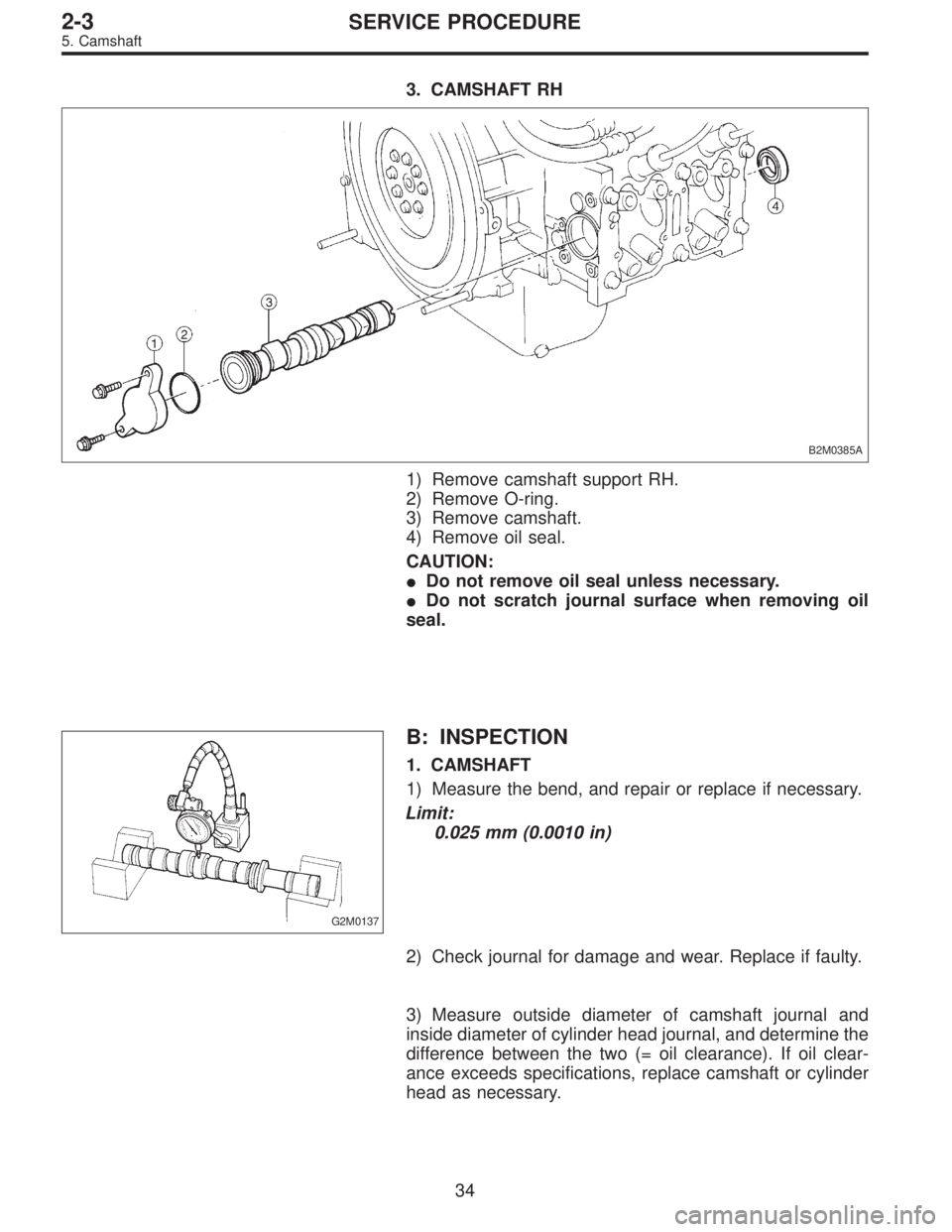
3. CAMSHAFT RH
B2M0385A
1) Remove camshaft support RH.
2) Remove O-ring.
3) Remove camshaft.
4) Remove oil seal.
CAUTION:
�Do not remove oil seal unless necessary.
�Do not scratch journal surface when removing oil
seal.
G2M0137
B: INSPECTION
1. CAMSHAFT
1) Measure the bend, and repair or replace if necessary.
Limit:
0.025 mm (0.0010 in)
2) Check journal for damage and wear. Replace if faulty.
3) Measure outside diameter of camshaft journal and
inside diameter of cylinder head journal, and determine the
difference between the two (= oil clearance). If oil clear-
ance exceeds specifications, replace camshaft or cylinder
head as necessary.
34
2-3SERVICE PROCEDURE
5. Camshaft
Page 297 of 3342

ItemRight-hand camshaft Front Center Rear
Left-hand camshaft Rear Center Front
Clearance at journalStandard 0.055—0.090 (0.0022—0.0035)
Limit 0.10 (0.0039 )
Camshaft journal O.D.31.9")
Unit: mm (in)
ItemRight-hand camshaft Front Center Rear
Left-hand camshaft Rear Center Front
Clearance at journalStandard 0.055—0.090 (0.0022—0.0035)
Limit 0.10 (0.0039 )
Camshaft journal O.D.31.935—31.950
(1.2573—1.2579)37.435—37.450
(1.4738—1.4744)37.935—37.950
(1.4935—1.4941)
Journal hole I.D.32.005—32.025
(1.2600—1.2608)37.505—37.525
(1.4766—1.4774)38.005—38.025
(1.4963—1.4970)
B2M1209A
4) Check cam face condition; remove minor faults by
grinding with oil stone. Measure the cam height H; replace
if the limit has been exceeded.
Cam height: H
Standard
IN: 32.244—32.344 mm (1.2694—1.2734 in)
EX: 31.964—32.064 mm (1.2584—1.2624 in)
Limit
IN: 32.094 mm (1.2635 in)
EX: 31.814 mm (1.2525 in)
Cam base circle diameter A:
IN: 27.5 mm (1.083 in)
EX: 27.0 mm (1.063 in)
G2M0139
2. CAMSHAFT SUPPORT
Measure the thrust clearance of camshaft with dial gauge.
If the clearance exceeds the limit, replace camshaft sup-
port.
Standard:
0.030—0.260 mm (0.0012—0.0102 in)
Limit:
0.35 mm (0.0138 in)
35
2-3SERVICE PROCEDURE
5. Camshaft
Page 305 of 3342
 Check the clearance between valve guide and stem.
The clearance can be checked by measuring the outside
diameter of valve stem and the inside diameter of valve
guid")
B2M0387A
B2M0076A
3. VALVE GUIDE
1) Check the clearance between valve guide and stem.
The clearance can be checked by measuring the outside
diameter of valve stem and the inside diameter of valve
guide with outside and inside micrometers respectively.
Clearance between the valve guide and valve stem:
Standard
Intake
0.035—0.062 mm (0.0014—0.0024 in)
Exhaust
0.040—0.067 mm (0.0016—0.0026 in)
Limit
0.15 mm (0.0059 in)
Valve guide inner diameter:
6.000—6.012 mm (0.2362—0.2367 in)
Valve stem outer diameters:
Intake
5.950—5.965 mm (0.2343—0.2348 in)
Exhaust
5.945—5.960 mm (0.2341—0.2346 in)
G2M0150
2) If the clearance between valve guide and stem exceeds
the specification, replace guide as follows:
(1) Place cylinder head on ST1 with the combustion
chamber upward so that valve guides enter the holes
in ST1.
(2) Insert ST2 into valve guide and press it down to
remove valve guide.
ST1 498267200 CYLINDER HEAD TABLE
ST2 499767200 VALVE GUIDE REMOVER
G2M0151
(3) Turn cylinder head upside down and place ST as
shown in the Figure.
ST 499767000 VALVE GUIDE ADJUSTER
B2M0388A
(4) Before installing new oversize valve guide, make
sure that neither scratches nor damages exist on the
inside surface of the valve guide holes in cylinder head.
(5) Put new valve guide, coated with sufficient oil, in
cylinder, and insert ST1 into valve guide. Press in until
the valve guide upper end is flush with the upper sur-
face of ST2.
ST1 499767200 VALVE GUIDE REMOVER
ST2 499767000 VALVE GUIDE ADJUSTER
42
2-3SERVICE PROCEDURE
6. Cylinder Head
Page 306 of 3342
B2M0077A
(6) Check the valve guide protrusion.
Valve guide protrusion: L
17.5—18.0 mm (0.689—0.709 in)
B2M0078
(7) Ream the inside of valve guide with ST. Gently
rotate the reamer clockwise while pressing it lightly into
valve guide, and return it also rotating clockwise. After
reaming, clean valve guide to remove chips.
ST 499767400 VALVE GUIDE REAMER
CAUTION:
�Apply engine oil to the reamer when reaming.
�If the inner surface of the valve guide is torn, the
edge of the reamer should be slightly ground with an
oil stone.
�If the inner surface of the valve guide becomes lus-
trous and the reamer does not chips, use a new reamer
or remedy the reamer.
(8) Recheck the contact condition between valve and
valve seat after replacing valve guide.
43
2-3SERVICE PROCEDURE
6. Cylinder Head
Page 307 of 3342
 Inspect the flange and stem of valve, and replace if
damaged, worn, or deformed, or if“H”is less than the
specified limit.
H:
Intake
Standard
1.0 mm (0.039 i")
G2M0153
4. INTAKE AND EXHAUST VALVE
1) Inspect the flange and stem of valve, and replace if
damaged, worn, or deformed, or if“H”is less than the
specified limit.
H:
Intake
Standard
1.0 mm (0.039 in)
Limit
0.8 mm (0.031 in)
Exhaust
Standard
1.2 mm (0.047 in)
Limit
0.8 mm (0.031 in)
Valve overall length:
Intake
101.0 mm (3.976 in)
Exhaust
101.2 mm (3.984 in)
2) Put a small amount of grinding compound on the seat
surface and lap the valve and seat surface. Also refer to 2.
VALVE SEAT 2-3 [W6C2] at this time. Install a new intake
valve oil seal after lapping.
G2M0154
5. VALVE SPRINGS
1) Check valve springs for damage, free length, and ten-
sion. Replace valve spring if it is not to the specifications
presented below.
2) To measure the squareness of the valve spring, stand
the spring on a surface plate and measure its deflection at
the top using a try square.
Free length 44.05 mm (1.7342 in)
Squareness 2.5°, 1.9 mm (0.075 in)
Tension/spring height174.6—200.1 N
(17.8—20.4 kg, 39.2—45.0 lb)/ 36.0 mm
(1.417 in)
405.0—458.0 N
(41.3—46.7 kg, 91.1—103.0 lb)/
28.2 mm (1.110 in)
44
2-3SERVICE PROCEDURE
6. Cylinder Head
Page 319 of 3342
C: INSPECTION
1. CYLINDER BLOCK
1) Check for cracks and damage visually. Especially,
inspect important parts by means of red lead check.
2) Check the oil passages for clogging.
3) Inspect crankcase surface that mates with cylinder
head for warping by using a straight edge, and correct by
grinding if necessary.
Warping limit:
0.05 mm (0.0020 in)
Grinding limit:
0.1 mm (0.004 in)
Standard height of cylinder block:
201.0 mm (7.91 in)
B2M0082A
2. CYLINDER AND PISTON
1) The cylinder bore size is stamped on the cylinder
block’s front upper surface.
NOTE:
Standard sized pistons are classified into two grades,“A”
and“B”. These grades should be used as a guide line in
selecting a standard piston.
Standard diameter:
A: 96.905—96.915 mm (3.8151—3.8155 in)
B: 96.895—96.905 mm (3.8148—3.8151 in)
56
2-3SERVICE PROCEDURE
7. Cylinder Block
Page 322 of 3342
 Check circlip installation groove on the piston for burr.
If necessary, remove burr from the groove so that piston
pin can lightly move.
5) Check piston pin circlip for distortion")
B2M0084A
B2M0420A
4) Check circlip installation groove on the piston for burr.
If necessary, remove burr from the groove so that piston
pin can lightly move.
5) Check piston pin circlip for distortion, cracks and wear.
G2M0623
4. PISTON RING
1) If piston ring is broken, damaged, or worn, or if its ten-
sion is insufficient, or when the piston is replaced, replace
piston ring with a new one of the same size as the piston.
CAUTION:
�“R”is marked on the end of the top and second
rings. When installing the rings to the piston, face this
mark upward.
G2M0624
�The oil ring is a combined ring consisting of two
rails and a spacer in between. When installing, be care-
ful to assemble correctly.
G2M0174
2) Squarely place piston ring and oil ring in cylinder, and
measure the piston ring gap with a thickness gauge.
Unit: mm (in)
Standard Limit
Piston
ring gapTop ring0.20—0.35
(0.0079—0.0138)1.0 (0.039)
Second ring0.20—0.50
(0.0079—0.0197)1.0 (0.039)
Oil ring rail0.20—0.70
(0.0079—0.0276)1.5 (0.059)
59
2-3SERVICE PROCEDURE
7. Cylinder Block
Page 325 of 3342
B2M0085
6) Inspect bushing at connecting rod small end, and
replace if worn or damaged. Also measure the piston pin
clearance at the connecting rod small end.
Clearance between piston pin and bushing:
Standard
0—0.022 mm (0—0.0009 in)
Limit
0.030 mm (0.0012 in)
B2M0084A
G2M0177
7) Replacement procedure is as follows.
(1) Remove bushing from connecting rod with ST and
press.
(2) Press bushing with ST after applying oil on the
periphery of bushing.
ST 499037100 CONNECTING ROD BUSHING
REMOVER AND INSTALLER
(3) Make two 3 mm (0.12 in) holes in bushing. Ream
the inside of bushing.
(4) After completion of reaming, clean bushing to
remove chips.
6. CRANKSHAFT AND CRANKSHAFT BEARING
1) Clean crankshaft completely and check for cracks by
means of red lead check etc., and replace if defective.
62
2-3SERVICE PROCEDURE
7. Cylinder Block
 Check the valve guide protrusion.
Valve guide protrusion: L
17.5—18.0 mm (0.689—0.709 in)
B2M0078
(7) Ream the inside of valve guide with ST. Gently
rotate the reamer clockwise while")
 Check for cracks and damage visually. Especially,
inspect important parts by means of red lead check.
2) Check the oil passages for clogging.
3) Inspect crankcase su")
 Inspect bushing at connecting rod small end, and
replace if worn or damaged. Also measure the piston pin
clearance at the connecting rod small end.
Clearance between piston pin and bushing:")