Page 2084 of 3342
10AO1
CHECK ENGINE/TRANSMISSION TYPE.
: Is engine/transmission type 2200 cc/MT?
: Check AT/MT identification circuit.
[T10DD0].>
: Go to step10AO2.
10AO2CHECK DTC P0106, P0107, P0108, P0403,
P1102, P1122 OR P1421 ON DISPLAY.
: Does the Subaru select monitor or OBD-II
general scan tool indicate DTC P0106,
P0107, P0108, P0403, P1102, P1122 or
P1421?
:�Inspect DTC P0106, P0107, P0108, P0403,
P1102, P1122 or P1421 using“10. Diagnostics
Chart with Trouble Code”.
�Manually check that EGR valve diaphragm is
not stuck.
WARNING:
Be careful when checking EGR valve, since it may be
extremely hot.
NOTE:
In this case, it is not necessary to inspect DTC P0400.
After checking the above item, go to
CONFIRMATION
OF ACTUAL DRIVING PATTERN.
: Go to step10AO3.
233
2-7ON-BOARD DIAGNOSTICS II SYSTEM
10. Diagnostic Chart with Trouble Code for LHD Vehicles
Page 2086 of 3342
B2M1095
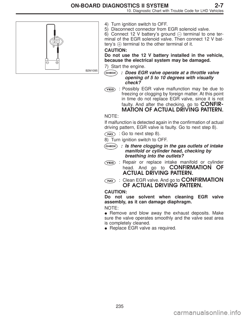
4) Turn ignition switch to OFF.
5) Disconnect connector from EGR solenoid valve.
6) Connect 12 V battery’s ground�terminal to one ter-
minal of the EGR solenoid valve. Then connect 12 V bat-
tery’s�terminal to the other terminal of it.
CAUTION:
Do not use the 12 V battery installed in the vehicle,
because the electrical system may be damaged.
7) Start the engine.
: Does EGR valve operate at a throttle valve
opening of 5 to 10 degrees with visually
check?
: Possibly EGR valve malfunction may be due to
freezing or clogging by foreign matter. At this point
in time do not replace EGR valve, since it is not
faulty. And after the checking, go to
CONFIR-
MATION OF ACTUAL DRIVING PATTERN.
NOTE:
If malfunction is detected again in the confirmation of actual
driving pattern, EGR valve is faulty. Go to next step 8).
: Go to next step 8).
8) Turn ignition switch to OFF.
: Is there clogging in the gas outlets of intake
manifold or cylinder head, checking by
breathing into the outlets?
: Repair or replace intake manifold or cylinder
head. And go to
CONFIRMATION OF
ACTUAL DRIVING PATTERN.
: Clean EGR valve. And go toCONFIRMATION
OF ACTUAL DRIVING PATTERN.
CAUTION:
Do not use solvent when cleaning EGR valve
assembly, as it can damage diaphragm.
NOTE:
�Remove and blow away the exhaust deposits. Make
sure the valve operates smoothly and the valve seat area
is completely cleaned.
�Replace EGR valve as required.
235
2-7ON-BOARD DIAGNOSTICS II SYSTEM
10. Diagnostic Chart with Trouble Code for LHD Vehicles
Page 2089 of 3342
![SUBARU LEGACY 1997 Service Repair Manual 10AP1
CHECK ENGINE/TRANSMISSION TYPE.
: Is engine/transmission type 2200 cc/MT?
: Check AT/MT identification circuit. <Ref. to 2-7
[T10DD0].>
: Go to step10AP2.
B2M0566A
10AP2
CHECK OUTPUT SIGNAL FROM SUBARU LEGACY 1997 Service Repair Manual 10AP1
CHECK ENGINE/TRANSMISSION TYPE.
: Is engine/transmission type 2200 cc/MT?
: Check AT/MT identification circuit. <Ref. to 2-7
[T10DD0].>
: Go to step10AP2.
B2M0566A
10AP2
CHECK OUTPUT SIGNAL FROM](/manual-img/17/57434/w960_57434-2088.png)
10AP1
CHECK ENGINE/TRANSMISSION TYPE.
: Is engine/transmission type 2200 cc/MT?
: Check AT/MT identification circuit.
[T10DD0].>
: Go to step10AP2.
B2M0566A
10AP2
CHECK OUTPUT SIGNAL FROM ECM.
1) Turn ignition switch to ON.
2) Measure voltage between ECM and chassis ground.
: Connector & terminal
(B84) No. 71 (+)—Chassis ground (�):
Is the voltage more than 10 V?
: Go to next.
: Go to step10AP3.
: Is there poor contact in ECM connector?
: Repair poor contact in ECM connector.
: Even if MIL lights up, the circuit has returned to a
normal condition at this time. (However, the pos-
sibility of poor contact still remains.)
NOTE:
In this case, repair the following:
�Poor contact in EGR solenoid valve connector
�Poor contact in ECM connector
�Poor contact in coupling connector (B21)
OBD0678A
10AP3CHECK HARNESS BETWEEN EGR
SOLENOID VALVE AND ECM CONNEC-
TOR.
1) Turn ignition switch to OFF.
2) Disconnect connectors from EGR solenoid valve and
ECM.
3) Measure resistance of harness between EGR solenoid
valve connector and engine ground.
: Connector & terminal
(E18) No. 2—Engine ground:
Is the resistance less than 10Ω?
: Repair ground short circuit in harness between
ECM and EGR solenoid valve connector.
: Go to next step 4).
238
2-7ON-BOARD DIAGNOSTICS II SYSTEM
10. Diagnostic Chart with Trouble Code for LHD Vehicles
Page 2090 of 3342
B2M0567A
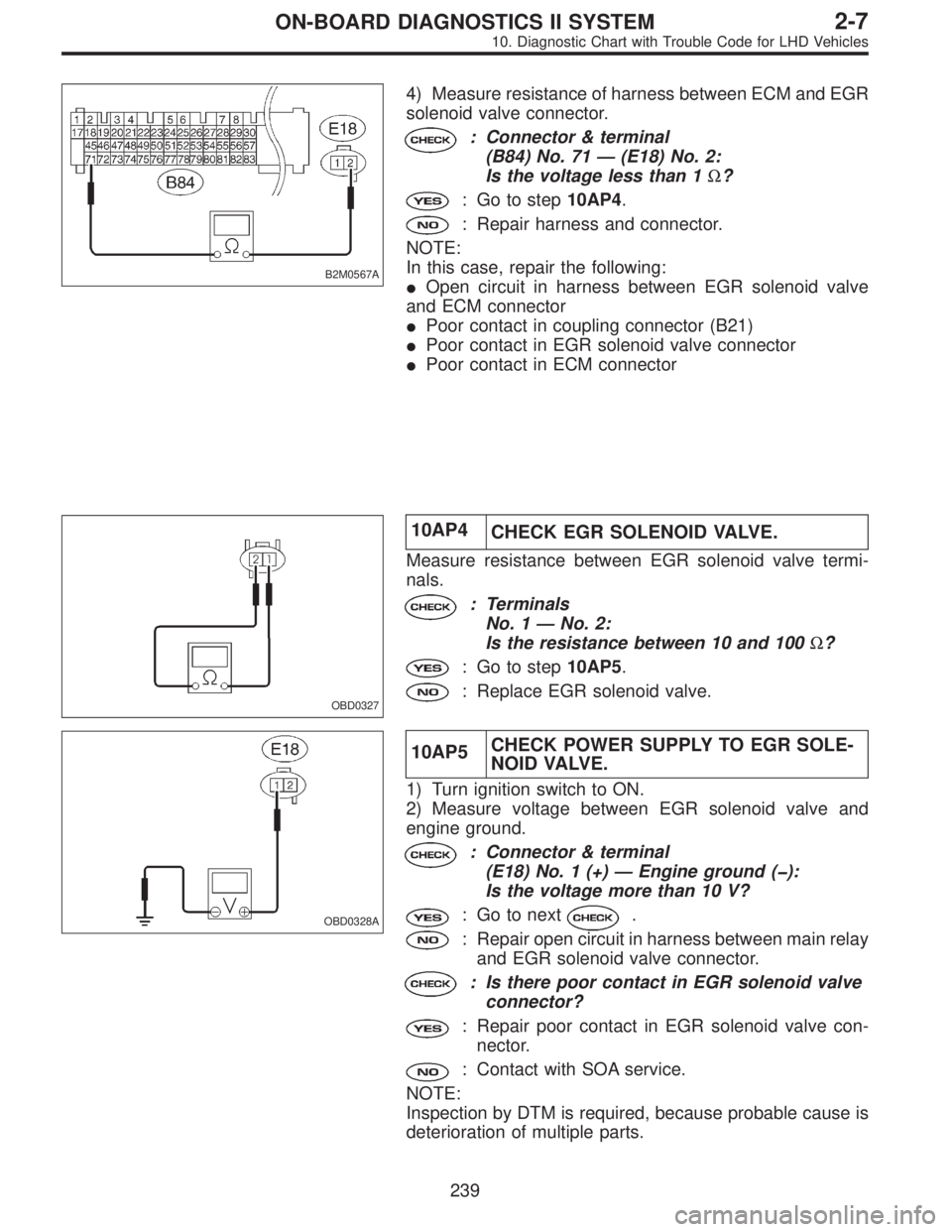
4) Measure resistance of harness between ECM and EGR
solenoid valve connector.
: Connector & terminal
(B84) No. 71—(E18) No. 2:
Is the voltage less than 1Ω?
: Go to step10AP4.
: Repair harness and connector.
NOTE:
In this case, repair the following:
�Open circuit in harness between EGR solenoid valve
and ECM connector
�Poor contact in coupling connector (B21)
�Poor contact in EGR solenoid valve connector
�Poor contact in ECM connector
OBD0327
10AP4
CHECK EGR SOLENOID VALVE.
Measure resistance between EGR solenoid valve termi-
nals.
: Terminals
No. 1—No. 2:
Is the resistance between 10 and 100Ω?
: Go to step10AP5.
: Replace EGR solenoid valve.
OBD0328A
10AP5CHECK POWER SUPPLY TO EGR SOLE-
NOID VALVE.
1) Turn ignition switch to ON.
2) Measure voltage between EGR solenoid valve and
engine ground.
: Connector & terminal
(E18) No. 1 (+)—Engine ground (�):
Is the voltage more than 10 V?
: Go to next.
: Repair open circuit in harness between main relay
and EGR solenoid valve connector.
: Is there poor contact in EGR solenoid valve
connector?
: Repair poor contact in EGR solenoid valve con-
nector.
: Contact with SOA service.
NOTE:
Inspection by DTM is required, because probable cause is
deterioration of multiple parts.
239
2-7ON-BOARD DIAGNOSTICS II SYSTEM
10. Diagnostic Chart with Trouble Code for LHD Vehicles
Page 2100 of 3342
B2M0570A
10AT1
CHECK OUTPUT SIGNAL FROM ECM.
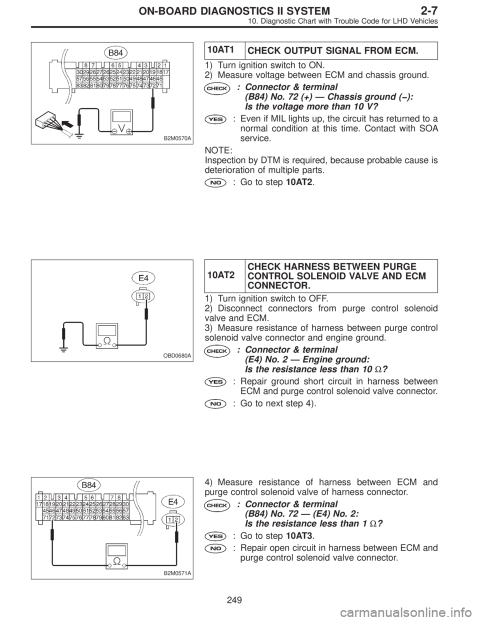
1) Turn ignition switch to ON.
2) Measure voltage between ECM and chassis ground.
: Connector & terminal
(B84) No. 72 (+)—Chassis ground (�):
Is the voltage more than 10 V?
: Even if MIL lights up, the circuit has returned to a
normal condition at this time. Contact with SOA
service.
NOTE:
Inspection by DTM is required, because probable cause is
deterioration of multiple parts.
: Go to step10AT2.
OBD0680A
10AT2CHECK HARNESS BETWEEN PURGE
CONTROL SOLENOID VALVE AND ECM
CONNECTOR.
1) Turn ignition switch to OFF.
2) Disconnect connectors from purge control solenoid
valve and ECM.
3) Measure resistance of harness between purge control
solenoid valve connector and engine ground.
: Connector & terminal
(E4) No. 2—Engine ground:
Is the resistance less than 10Ω?
: Repair ground short circuit in harness between
ECM and purge control solenoid valve connector.
: Go to next step 4).
B2M0571A
4) Measure resistance of harness between ECM and
purge control solenoid valve of harness connector.
: Connector & terminal
(B84) No. 72—(E4) No. 2:
Is the resistance less than 1Ω?
: Go to step10AT3.
: Repair open circuit in harness between ECM and
purge control solenoid valve connector.
249
2-7ON-BOARD DIAGNOSTICS II SYSTEM
10. Diagnostic Chart with Trouble Code for LHD Vehicles
Page 2101 of 3342
OBD0338
10AT3CHECK PURGE CONTROL SOLENOID
VA LV E .
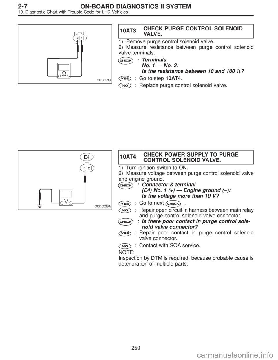
1) Remove purge control solenoid valve.
2) Measure resistance between purge control solenoid
valve terminals.
: Terminals
No. 1—No. 2:
Is the resistance between 10 and 100Ω?
: Go to step10AT4.
: Replace purge control solenoid valve.
OBD0339A
10AT4CHECK POWER SUPPLY TO PURGE
CONTROL SOLENOID VALVE.
1) Turn ignition switch to ON.
2) Measure voltage between purge control solenoid valve
and engine ground.
: Connector & terminal
(E4) No. 1 (+)—Engine ground (�):
Is the voltage more than 10 V?
: Go to next.
: Repair open circuit in harness between main relay
and purge control solenoid valve connector.
: Is there poor contact in purge control sole-
noid valve connector?
: Repair poor contact in purge control solenoid
valve connector.
: Contact with SOA service.
NOTE:
Inspection by DTM is required, because probable cause is
deterioration of multiple parts.
250
2-7ON-BOARD DIAGNOSTICS II SYSTEM
10. Diagnostic Chart with Trouble Code for LHD Vehicles
Page 2122 of 3342
H2M1414B
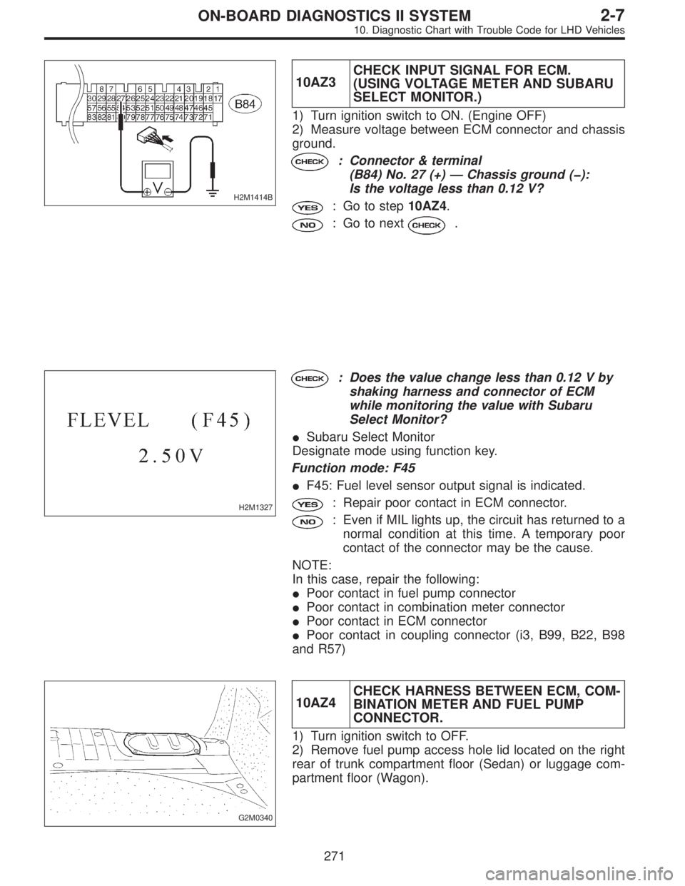
10AZ3CHECK INPUT SIGNAL FOR ECM.
(USING VOLTAGE METER AND SUBARU
SELECT MONITOR.)
1) Turn ignition switch to ON. (Engine OFF)
2) Measure voltage between ECM connector and chassis
ground.
: Connector & terminal
(B84) No. 27 (+)—Chassis ground (�):
Is the voltage less than 0.12 V?
: Go to step10AZ4.
: Go to next.
H2M1327
: Does the value change less than 0.12 V by
shaking harness and connector of ECM
while monitoring the value with Subaru
Select Monitor?
�Subaru Select Monitor
Designate mode using function key.
Function mode: F45
�F45: Fuel level sensor output signal is indicated.
: Repair poor contact in ECM connector.
: Even if MIL lights up, the circuit has returned to a
normal condition at this time. A temporary poor
contact of the connector may be the cause.
NOTE:
In this case, repair the following:
�Poor contact in fuel pump connector
�Poor contact in combination meter connector
�Poor contact in ECM connector
�Poor contact in coupling connector (i3, B99, B22, B98
and R57)
G2M0340
10AZ4CHECK HARNESS BETWEEN ECM, COM-
BINATION METER AND FUEL PUMP
CONNECTOR.
1) Turn ignition switch to OFF.
2) Remove fuel pump access hole lid located on the right
rear of trunk compartment floor (Sedan) or luggage com-
partment floor (Wagon).
271
2-7ON-BOARD DIAGNOSTICS II SYSTEM
10. Diagnostic Chart with Trouble Code for LHD Vehicles
Page 2128 of 3342
H2M1414B
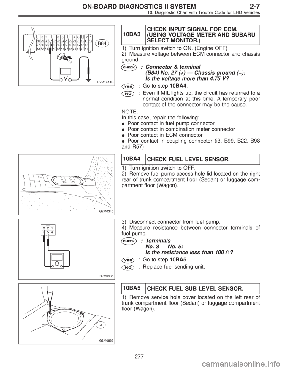
10BA3CHECK INPUT SIGNAL FOR ECM.
(USING VOLTAGE METER AND SUBARU
SELECT MONITOR.)
1) Turn ignition switch to ON. (Engine OFF)
2) Measure voltage between ECM connector and chassis
ground.
: Connector & terminal
(B84) No. 27 (+)—Chassis ground (�):
Is the voltage more than 4.75 V?
: Go to step10BA4.
: Even if MIL lights up, the circuit has returned to a
normal condition at this time. A temporary poor
contact of the connector may be the cause.
NOTE:
In this case, repair the following:
�Poor contact in fuel pump connector
�Poor contact in combination meter connector
�Poor contact in ECM connector
�Poor contact in coupling connector (i3, B99, B22, B98
and R57)
G2M0340
10BA4
CHECK FUEL LEVEL SENSOR.
1) Turn ignition switch to OFF.
2) Remove fuel pump access hole lid located on the right
rear of trunk compartment floor (Sedan) or luggage com-
partment floor (Wagon).
B2M0935
3) Disconnect connector from fuel pump.
4) Measure resistance between connector terminals of
fuel pump.
: Terminals
No. 3—No. 5:
Is the resistance less than 100Ω?
: Go to step10BA5.
: Replace fuel sending unit.
G2M0863
10BA5
CHECK FUEL SUB LEVEL SENSOR.
1) Remove service hole cover located on the left rear of
trunk compartment floor (Sedan) or luggage compartment
floor (Wagon).
277
2-7ON-BOARD DIAGNOSTICS II SYSTEM
10. Diagnostic Chart with Trouble Code for LHD Vehicles