Page 2192 of 3342

: Repair poor contact in ECM connector.
: Contact with SOA service.
NOTE:
Inspection by DTM is required, because probable cause is
deterioration of multiple parts.
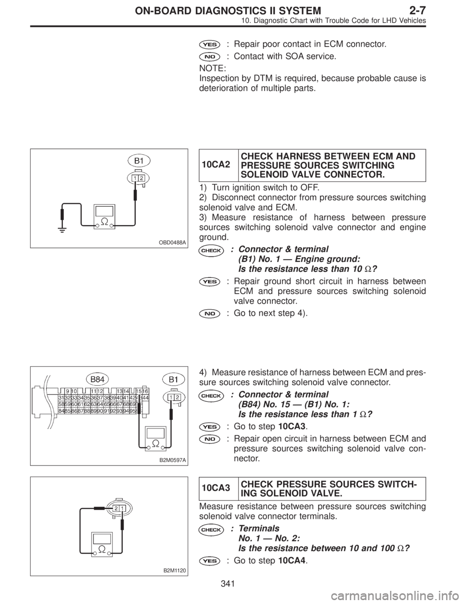
OBD0488A
10CA2CHECK HARNESS BETWEEN ECM AND
PRESSURE SOURCES SWITCHING
SOLENOID VALVE CONNECTOR.
1) Turn ignition switch to OFF.
2) Disconnect connector from pressure sources switching
solenoid valve and ECM.
3) Measure resistance of harness between pressure
sources switching solenoid valve connector and engine
ground.
: Connector & terminal
(B1) No. 1—Engine ground:
Is the resistance less than 10Ω?
: Repair ground short circuit in harness between
ECM and pressure sources switching solenoid
valve connector.
: Go to next step 4).
B2M0597A
4) Measure resistance of harness between ECM and pres-
sure sources switching solenoid valve connector.
: Connector & terminal
(B84) No. 15—(B1) No. 1:
Is the resistance less than 1Ω?
: Go to step10CA3.
: Repair open circuit in harness between ECM and
pressure sources switching solenoid valve con-
nector.
B2M1120
10CA3CHECK PRESSURE SOURCES SWITCH-
ING SOLENOID VALVE.
Measure resistance between pressure sources switching
solenoid valve connector terminals.
: Terminals
No. 1—No. 2:
Is the resistance between 10 and 100Ω?
: Go to step10CA4.
341
2-7ON-BOARD DIAGNOSTICS II SYSTEM
10. Diagnostic Chart with Trouble Code for LHD Vehicles
Page 2193 of 3342
: Replace pressure sources switching solenoid
valve.
OBD0676A
10CA4CHECK POWER SUPPLY TO PRESSURE
SOURCES SWITCHING SOLENOID
VA LV E .
1) Turn ignition switch to ON.
2) Measure voltage between pressure sources switching
solenoid valve harness connector and engine ground.
: Connector & terminal
(B1) No. 2 (+)—Engine ground (�):
Is the voltage more than 10 V?
: Go to next.
: Repair open circuit in harness between main relay
and pressure sources switching solenoid valve
connector.
: Is there poor contact in pressure sources
switching solenoid valve connector?
: Repair poor contact in pressure sources switching
solenoid valve connector.
: Contact with SOA service.
NOTE:
Inspection by DTM is required, because probable cause is
deterioration of multiple parts.
342
2-7ON-BOARD DIAGNOSTICS II SYSTEM
10. Diagnostic Chart with Trouble Code for LHD Vehicles
Page 2203 of 3342

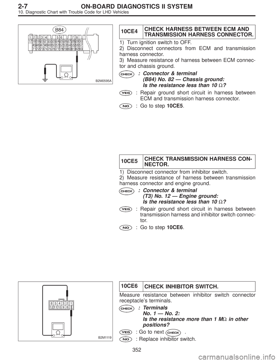
B2M0595A
10CE4CHECK HARNESS BETWEEN ECM AND
TRANSMISSION HARNESS CONNECTOR.
1) Turn ignition switch to OFF.
2) Disconnect connectors from ECM and transmission
harness connector.
3) Measure resistance of harness between ECM connec-
tor and chassis ground.
: Connector & terminal
(B84) No. 82—Chassis ground:
Is the resistance less than 10Ω?
: Repair ground short circuit in harness between
ECM and transmission harness connector.
: Go to step10CE5.
10CE5CHECK TRANSMISSION HARNESS CON-
NECTOR.
1) Disconnect connector from inhibitor switch.
2) Measure resistance of harness between transmission
harness connector and engine ground.
: Connector & terminal
(T3) No. 12—Engine ground:
Is the resistance less than 10Ω?
: Repair ground short circuit in harness between
transmission harness and inhibitor switch connec-
tor.
: Go to step10CE6.
B2M1119
10CE6
CHECK INHIBITOR SWITCH.
Measure resistance between inhibitor switch connector
receptacle’s terminals.
: Terminals
No. 1—No. 2:
Is the resistance more than 1 MΩin other
positions?
: Go to next.
: Replace inhibitor switch.
352
2-7ON-BOARD DIAGNOSTICS II SYSTEM
10. Diagnostic Chart with Trouble Code for LHD Vehicles
Page 2210 of 3342

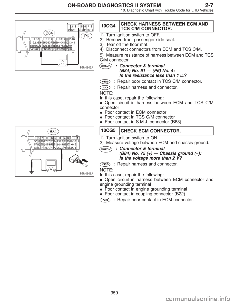
B2M0605A
10CG4CHECK HARNESS BETWEEN ECM AND
TCS C/M CONNECTOR.
1) Turn ignition switch to OFF.
2) Remove front passenger side seat.
3) Tear off the floor mat.
4) Disconnect connectors from ECM and TCS C/M.
5) Measure resistance of harness between ECM and TCS
C/M connector.
: Connector & terminal
(B84) No. 61—(P6) No. 4:
Is the resistance less than 1Ω?
: Repair poor contact in TCS C/M connector.
: Repair harness and connector.
NOTE:
In this case, repair the following:
�Open circuit in harness between ECM and TCS C/M
connector
�Poor contact in ECM connector
�Poor contact in TCS C/M connector
�Poor contact in S.M.J. connector (B63)
B2M0606A
10CG5
CHECK ECM CONNECTOR.
1) Turn ignition switch to ON.
2) Measure voltage between ECM and chassis ground.
: Connector & terminal
(B84) No. 75 (+)—Chassis ground (�):
Is the voltage more than 2 V?
: Repair harness and connector.
NOTE:
In this case, repair the following:
�Open circuit in harness between ECM connector and
engine grounding terminal
�Poor contact in engine grounding terminal
�Poor contact in coupling connector (B22)
: Repair poor contact in ECM connector.
359
2-7ON-BOARD DIAGNOSTICS II SYSTEM
10. Diagnostic Chart with Trouble Code for LHD Vehicles
Page 2216 of 3342
OBD0145A
B2M0755
10CJ1
CHECK DATA FOR CONTROL.
1) Turn ignition switch to OFF.
2) Connect Subaru Select Monitor or the OBD-II general
scan tool to data link connector.
3) Turn ignition switch ON and Subaru Select Monitor or
the OBD-II general scan tool switch ON.
4) Start engine.
5) Read data on Subaru Select Monitor or the OBD-II gen-
eral scan tool.
�Subaru Select Monitor
Designate mode using function key.
Function mode: F20
�F20: Display shows pressure signal value sent from the
pressure sensor.
: Is the value less than 32 kPa in function
mode F20?
: Go to step10CJ3.
: Go to step10CJ2.
�OBD-II general scan tool
For detailed operation procedures, refer to the OBD-II Gen-
eral Scan Tool Instruction Manual.
365
2-7ON-BOARD DIAGNOSTICS II SYSTEM
10. Diagnostic Chart with Trouble Code for LHD Vehicles
Page 2220 of 3342

OBD0145A
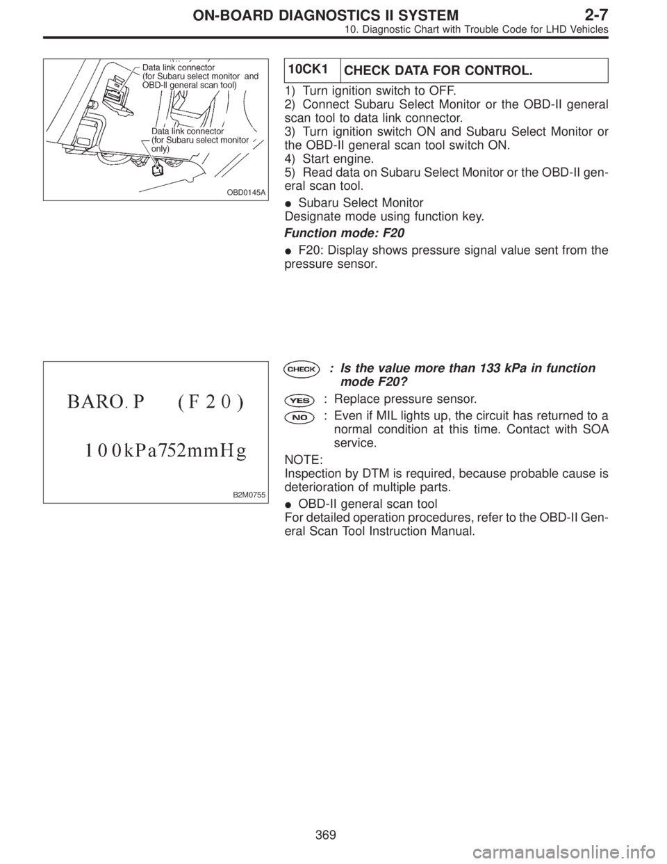
10CK1
CHECK DATA FOR CONTROL.
1) Turn ignition switch to OFF.
2) Connect Subaru Select Monitor or the OBD-II general
scan tool to data link connector.
3) Turn ignition switch ON and Subaru Select Monitor or
the OBD-II general scan tool switch ON.
4) Start engine.
5) Read data on Subaru Select Monitor or the OBD-II gen-
eral scan tool.
�Subaru Select Monitor
Designate mode using function key.
Function mode: F20
�F20: Display shows pressure signal value sent from the
pressure sensor.
B2M0755
: Is the value more than 133 kPa in function
mode F20?
: Replace pressure sensor.
: Even if MIL lights up, the circuit has returned to a
normal condition at this time. Contact with SOA
service.
NOTE:
Inspection by DTM is required, because probable cause is
deterioration of multiple parts.
�OBD-II general scan tool
For detailed operation procedures, refer to the OBD-II Gen-
eral Scan Tool Instruction Manual.
369
2-7ON-BOARD DIAGNOSTICS II SYSTEM
10. Diagnostic Chart with Trouble Code for LHD Vehicles
Page 2229 of 3342
![SUBARU LEGACY 1997 Service Repair Manual 10CN1
CHECK ENGINE/TRANSMISSION TYPE.
: Is engine/transmission type 2200 cc/MT?
: Check AT/MT identification circuit. <Ref. to 2-7
[T10DD0].>
: Go to step10CN2.
B2M0566A
10CN2
CHECK OUTPUT SIGNAL FROM SUBARU LEGACY 1997 Service Repair Manual 10CN1
CHECK ENGINE/TRANSMISSION TYPE.
: Is engine/transmission type 2200 cc/MT?
: Check AT/MT identification circuit. <Ref. to 2-7
[T10DD0].>
: Go to step10CN2.
B2M0566A
10CN2
CHECK OUTPUT SIGNAL FROM](/manual-img/17/57434/w960_57434-2228.png)
10CN1
CHECK ENGINE/TRANSMISSION TYPE.
: Is engine/transmission type 2200 cc/MT?
: Check AT/MT identification circuit.
[T10DD0].>
: Go to step10CN2.
B2M0566A
10CN2
CHECK OUTPUT SIGNAL FROM ECM.
1) Turn ignition switch to ON.
2) Measure voltage between ECM and chassis ground.
: Connector & terminal
(B84) No. 71 (+)—Chassis ground (�):
Is the voltage more than 10 V?
: Go to step10CN3.
: Go to next.
: Is there poor contact in ECM connector?
: Repair poor contact in ECM connector.
: Replace ECM.
B2M0566A
10CN3CHECK HARNESS BETWEEN EGR
SOLENOID VALVE AND ECM CONNEC-
TOR.
1) Turn ignition switch to OFF.
2) Disconnect connector from EGR solenoid valve.
3) Turn ignition switch to ON.
4) Measure voltage between ECM and chassis ground.
: Connector & terminal
(B84) No. 71 (+)—Chassis ground (�):
Is the voltage more than 10 V?
: Repair battery short circuit in harness between
ECM and EGR solenoid valve connector. After
repair, replace ECM.
: Go to next step 5).
378
2-7ON-BOARD DIAGNOSTICS II SYSTEM
10. Diagnostic Chart with Trouble Code for LHD Vehicles
Page 2253 of 3342
CAUTION:
After repair or replacement of faulty parts, conduct
CLEAR MEMORY and INSPECTION MODES.
NOTE:
If the vehicle, with the engine idling, is placed very close to
a wall or another vehicle, preventing normal cooling
function, the OBD system may detect malfunction.
10CU1CHECK ANY OTHER DTC (BESIDE DTC
P1502) ON DISPLAY.
: Is there any other DTC on display?
: Inspect the relevant DTC using“10. Diagnostics
Chart with Trouble Code”.
: Check engine cooling system.
[K100].>
402
2-7ON-BOARD DIAGNOSTICS II SYSTEM
10. Diagnostic Chart with Trouble Code for LHD Vehicles