Page 2059 of 3342
DTC DETECTING CONDITION:
�Immediately at fault recognition
TROUBLE SYMPTOM:
�Failure of engine to start
�Engine stalls.
�Erroneous idling
�Rough driving
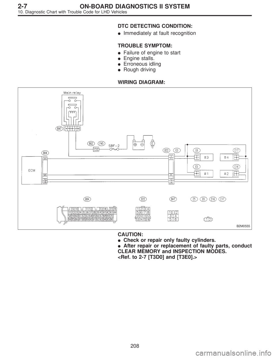
WIRING DIAGRAM:
B2M0555
CAUTION:
�Check or repair only faulty cylinders.
�After repair or replacement of faulty parts, conduct
CLEAR MEMORY and INSPECTION MODES.
208
2-7ON-BOARD DIAGNOSTICS II SYSTEM
10. Diagnostic Chart with Trouble Code for LHD Vehicles
Page 2065 of 3342
 Start engine, and drive the vehicle more than 10 min-
utes.
: Is the MIL coming on or blinking?
: Go to step10AI3.
: Go to next.
: Has the vehicle been run empty of fuel?
: Finish diagnost")
OBD0008C
7) Start engine, and drive the vehicle more than 10 min-
utes.
: Is the MIL coming on or blinking?
: Go to step10AI3.
: Go to next.
: Has the vehicle been run empty of fuel?
: Finish diagnostics operation, if the engine has no
abnormality.
: Go to next.
: Was the cause of misfire diagnosed when
the engine is running?
NOTE:
Ex. Remove spark plug cord, etc.
: Finish diagnostics operation, if the engine has no
abnormality.
: Repair connector.
NOTE:
In this case, repair the following:
�Poor contact in ignitor connector
�Poor contact in ignition coil connector
�Poor contact in fuel injector connector on faulty cylinders
�Poor contact in ECM connector
�Poor contact in coupling connector (B22)
10AI3
CHECK AIR INTAKE SYSTEM.
: Is there a fault in air intake system?
NOTE:
Check the following items:
�Are there air leaks or air suction caused by loose or dis-
located nuts and bolts?
�Are there cracks or any disconnection of hoses?
: Repair air intake system.
: Go to step10AI4.
OBD0145A
10AI4
CHECK MISFIRE SYMPTOM.
1) Turn ignition switch to OFF.
2) Connect the Subaru Select Monitor or the OBD-II gen-
eral scan tool to data link connector.
3) Turn ignition switch to ON, and turn Subaru Select
Monitor or OBD-II general scan tool switch to ON.
214
2-7ON-BOARD DIAGNOSTICS II SYSTEM
10. Diagnostic Chart with Trouble Code for LHD Vehicles
Page 2069 of 3342
10AI9
GROUP OF #2 AND #4 CYLINDERS
: Are there faults in #2 and #4 cylinders?
NOTE:
Check the following items.
�Spark plugs
�Fuel injectors
�Skipping timing belt teeth
: Repair or replace faulty parts.
: Go to step10AI11.
10AI10
THE CYLINDER AT RANDOM
: Is the engine idle rough?
: Go to step10AI11.
: Go to DTC P0170.
and [T10T5].>
B2M0759
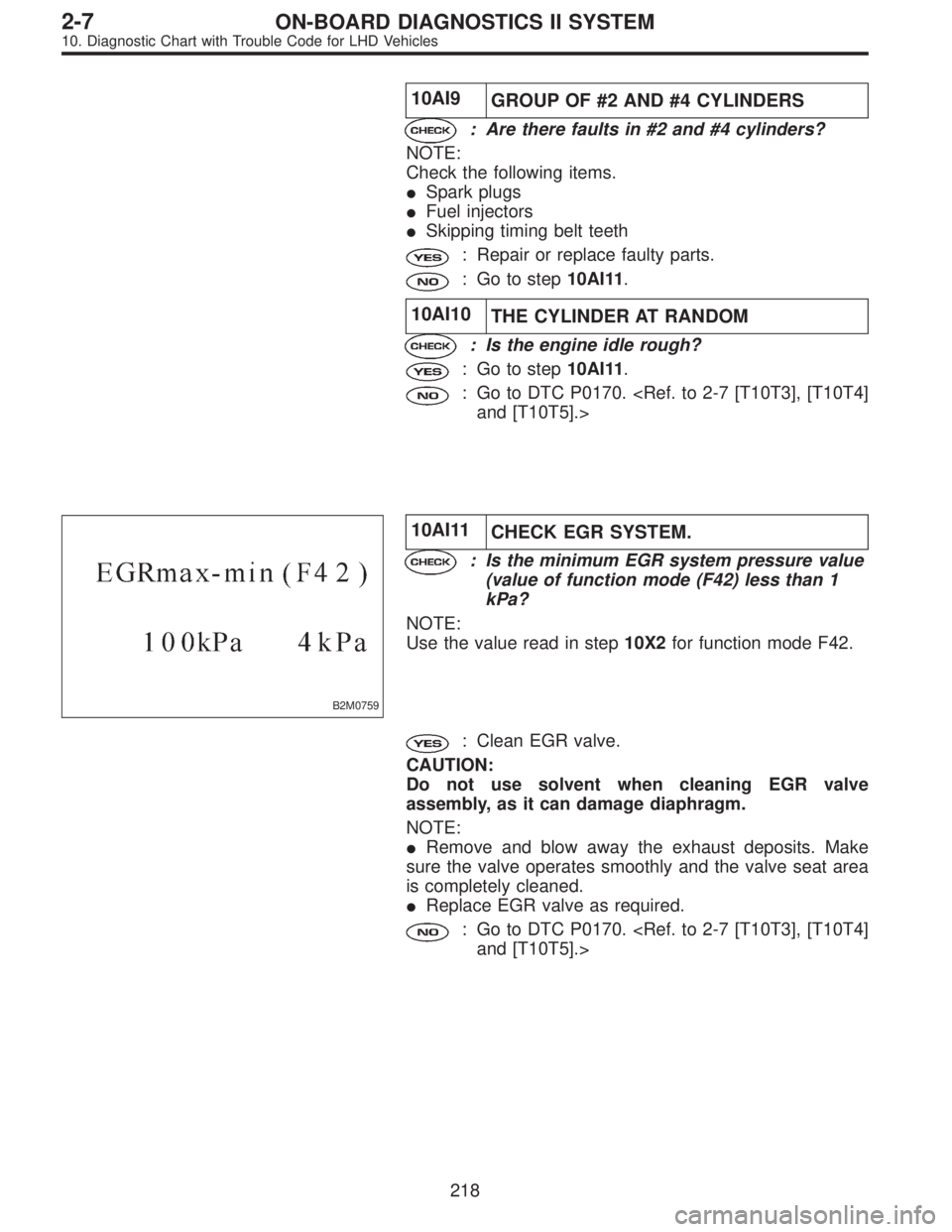
10AI11
CHECK EGR SYSTEM.
: Is the minimum EGR system pressure value
(value of function mode (F42) less than 1
kPa?
NOTE:
Use the value read in step10X2for function mode F42.
: Clean EGR valve.
CAUTION:
Do not use solvent when cleaning EGR valve
assembly, as it can damage diaphragm.
NOTE:
�Remove and blow away the exhaust deposits. Make
sure the valve operates smoothly and the valve seat area
is completely cleaned.
�Replace EGR valve as required.
: Go to DTC P0170.
and [T10T5].>
218
2-7ON-BOARD DIAGNOSTICS II SYSTEM
10. Diagnostic Chart with Trouble Code for LHD Vehicles
Page 2071 of 3342
 Turn ignition switch to OFF.
2) Disconnect connector from ECM.
3) Measure resistance between ECM harness connector
and chassis gr")
B2M0560A
10AJ1CHECK HARNESS BETWEEN KNOCK
SENSOR AND ECM CONNECTOR.
1) Turn ignition switch to OFF.
2) Disconnect connector from ECM.
3) Measure resistance between ECM harness connector
and chassis ground.
: Connector & terminal
(B84) No. 3—Chassis ground:
Is the resistance more than 700 kΩ?
: Go to step10AJ2.
: Go to next.
B2M0560A
: Connector & terminal
(B84) No. 3—Chassis ground:
Is the resistance less than 400 kΩ?
: Go to step10AJ3.
: Go to step10AJ4.
B2M1090
10AJ2
CHECK KNOCK SENSOR.
1) Disconnect connector from knock sensor.
2) Measure resistance between knock sensor connector
terminal and engine ground.
: Terminal
No. 2—Engine ground:
Is the resistance more than 700 kΩ?
: Go to next.
: Repair harness and connector.
NOTE:
In this case, repair the following:
�Open circuit in harness between knock sensor and ECM
connector
�Poor contact in knock sensor connector
�Poor contact in coupling connector (B21)
: Is the knock sensor installation bolt tight-
ened securely?
: Replace knock sensor.
: Tighten knock sensor installation bolt securely.
220
2-7ON-BOARD DIAGNOSTICS II SYSTEM
10. Diagnostic Chart with Trouble Code for LHD Vehicles
Page 2072 of 3342
 Disconnect connector from knock sensor.
2) Measure resistance between knock sensor connector
terminal and engine ground.
: Terminal
No. 2—Engine ground:
Is the r")
B2M1090
10AJ3
CHECK KNOCK SENSOR.
1) Disconnect connector from knock sensor.
2) Measure resistance between knock sensor connector
terminal and engine ground.
: Terminal
No. 2—Engine ground:
Is the resistance less than 400 kΩ?
: Replace knock sensor.
: Repair ground short circuit in harness between
knock sensor connector and ECM connector.
NOTE:
The harness between both connectors is shielded. Repair
short circuit of harness together with shield.
B2M0561A
10AJ4
CHECK INPUT SIGNAL FOR ECM.
1) Connect connectors to ECM and knock sensor.
2) Turn ignition switch to ON.
3) Measure voltage between ECM and chassis ground.
: Connector & terminal
(B84) No. 3 (+)—Chassis ground (�):
Is the voltage more than 2 V?
: Even if MIL lights up, the circuit has returned to a
normal condition at this time. (However, the pos-
sibility of poor contact still remains.)
NOTE:
In this case, repair the following:
�Poor contact in knock sensor connector
�Poor contact in ECM connector
�Poor contact in coupling connector (B21)
: Repair poor contact in ECM connector.
221
2-7ON-BOARD DIAGNOSTICS II SYSTEM
10. Diagnostic Chart with Trouble Code for LHD Vehicles
Page 2074 of 3342
 Turn ignition switch to OFF.
2) Disconnect connector from crankshaft position sensor.
3) Measure resistance of ha")
OBD0718A
10AK1CHECK HARNESS BETWEEN CRANK-
SHAFT POSITION SENSOR AND ECM
CONNECTOR.
1) Turn ignition switch to OFF.
2) Disconnect connector from crankshaft position sensor.
3) Measure resistance of harness between crankshaft
position sensor connector and engine ground.
: Connector & terminal
(E10) No. 1—Engine ground:
Is the resistance more than 100 kΩ?
: Repair harness and connector.
NOTE:
In this case, repair the following:
�Open circuit in harness between crankshaft position
sensor and ECM connector
�Poor contact in ECM connector
�Poor contact in coupling connector (B20)
: Go to next.
OBD0718A
: Connector & terminal
(E10) No. 1—Engine ground:
Is the resistance less than 10Ω?
: Repair ground short circuit in harness between
crankshaft position sensor and ECM connector.
NOTE:
The harness between both connectors are shielded.
Repair ground short circuit in harness together with shield.
: Go to next.
OBD0719A
: Connector & terminal
(E10) No. 2—Engine ground:
Is the resistance less than 5Ω?
: Go to step10AK2.
: Repair harness and connector.
NOTE:
In this case, repair the following:
�Open circuit in harness between crankshaft position
sensor and ECM connector
�Poor contact in ECM connector
�Poor contact in coupling connector (B20)
223
2-7ON-BOARD DIAGNOSTICS II SYSTEM
10. Diagnostic Chart with Trouble Code for LHD Vehicles
Page 2079 of 3342
 Turn ignition switch to OFF.
2) Disconnect connector from camshaft position sensor.
3) Measure resistance of harnes")
OBD0720A
10AM1CHECK HARNESS BETWEEN CAM-
SHAFT POSITION SENSOR AND ECM
CONNECTOR.
1) Turn ignition switch to OFF.
2) Disconnect connector from camshaft position sensor.
3) Measure resistance of harness between camshaft posi-
tion sensor connector and engine ground.
: Connector & terminal
(E15) No. 1—Engine ground:
Is the resistance more than 100 kΩ?
: Repair harness and connector.
NOTE:
In this case, repair the following:
�Open circuit in harness between camshaft position sen-
sor and ECM connector
�Poor contact in ECM connector
�Poor contact in coupling connector (B20)
: Go to next.
OBD0720A
: Connector & terminal
(E15) No. 1—Engine ground:
Is the resistance less than 10Ω?
: Repair ground short circuit in harness between
camshaft position sensor connector and ECM
connector.
NOTE:
The harness between both connectors are shielded.
Repair ground short circuit in harness together with shield.
: Go to next.
228
2-7ON-BOARD DIAGNOSTICS II SYSTEM
10. Diagnostic Chart with Trouble Code for LHD Vehicles
Page 2080 of 3342
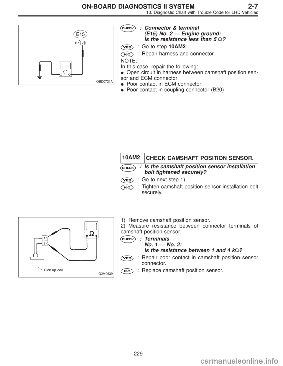
OBD0721A
: Connector & terminal
(E15) No. 2—Engine ground:
Is the resistance less than 5Ω?
: Go to step10AM2.
: Repair harness and connector.
NOTE:
In this case, repair the following:
�Open circuit in harness between camshaft position sen-
sor and ECM connector
�Poor contact in ECM connector
�Poor contact in coupling connector (B20)
10AM2
CHECK CAMSHAFT POSITION SENSOR.
: Is the camshaft position sensor installation
bolt tightened securely?
: Go to next step 1).
: Tighten camshaft position sensor installation bolt
securely.
G2M0639
1) Remove camshaft position sensor.
2) Measure resistance between connector terminals of
camshaft position sensor.
: Terminals
No. 1—No. 2:
Is the resistance between 1 and 4 kΩ?
: Repair poor contact in camshaft position sensor
connector.
: Replace camshaft position sensor.
229
2-7ON-BOARD DIAGNOSTICS II SYSTEM
10. Diagnostic Chart with Trouble Code for LHD Vehicles