Page 2135 of 3342
 Turn ignition switch to ON.
2) Start engine, and idle it.
: Is there a fault in air intake system?
NOTE:
Check the following items.
�Loose installation of intake mani")
10BC1
CHECK AIR INTAKE SYSTEM.
1) Turn ignition switch to ON.
2) Start engine, and idle it.
: Is there a fault in air intake system?
NOTE:
Check the following items.
�Loose installation of intake manifold, idle air control sole-
noid valve and throttle body
�Cracks of intake manifold gasket, idle air control sole-
noid valve gasket and throttle body gasket
�Loose connections and cracks of idle air control solenoid
valve by-pass hoses
�Disconnections of vacuum hoses
: Repair or replace air intake system.
: Go to step10BC2.
B2M0576A
10BC2
CHECK OUTPUT SIGNAL FROM ECM.
1) Turn ignition switch to ON.
2) Measure voltage between ECM and chassis ground.
: Connector & terminal
(B84) No. 13 (+)—Chassis ground (�):
Is the voltage more than 3 V?
: Go to next.
: Go to step10BC4.
: Connector & terminal
(B84) No. 14 (+)—Chassis ground (�):
Is the voltage more than 3 V?
: Go to next step 3).
: Go to step10BC4.
284
2-7ON-BOARD DIAGNOSTICS II SYSTEM
10. Diagnostic Chart with Trouble Code for LHD Vehicles
Page 2138 of 3342
 Turn ignition switch to OFF.
2) Disconnect connector from idle air control solenoid
valve.
3) Turn ignition switch to ON.
4) Mea")
B2M0578A
10BC4CHECK POWER SUPPLY TO IDLE AIR
CONTROL SOLENOID VALVE.
1) Turn ignition switch to OFF.
2) Disconnect connector from idle air control solenoid
valve.
3) Turn ignition switch to ON.
4) Measure voltage between idle air control solenoid valve
and engine ground.
: Connector & terminal
(E7) No. 2 (+)—Engine ground (�):
Is the voltage more than 10 V?
: Go to step10BC5.
: Repair open circuit in harness between idle air
control solenoid valve and main relay connector.
B2M0579A
10BC5CHECK HARNESS BETWEEN ECM AND
IDLE AIR CONTROL SOLENOID VALVE
CONNECTOR.
1) Turn ignition switch to OFF.
2) Disconnect connector from ECM.
3) Measure resistance of harness between ECM and idle
air control solenoid valve connector.
: Connector & terminal
(B84) No. 14—(E7) No. 1:
Is the resistance less than 1Ω?
: Go to next.
: Repair open circuit in harness between ECM and
idle air control solenoid valve connector.
: Connector & terminal
(B84) No. 13—(E7) No. 3:
Is the resistance less than 1Ω?
: Go to next step 4).
: Repair open circuit in harness between ECM and
idle air control solenoid valve connector.
B2M0580A
4) Measure resistance of harness between ECM and
chassis ground.
: Connector & terminal
(B84) No. 13—Chassis ground:
Is the resistance less than 10Ω?
: Repair ground short circuit in harness between
ECM and idle air control solenoid valve connector.
: Go to next.
287
2-7ON-BOARD DIAGNOSTICS II SYSTEM
10. Diagnostic Chart with Trouble Code for LHD Vehicles
Page 2141 of 3342
10BD1
CHECK DTC P0505 ON DISPLAY.
: Does the Subaru select monitor or OBD-II
general scan tool indicate DTC P0505?
: Inspect DTC P0505 using“10. Diagnostics Chart
with Trouble Code”.
NOTE:
In this case, it is not necessary to inspect DTC P0506.
: Go to step10BD2.
10BD2
CHECK AIR INTAKE SYSTEM.
1) Turn ignition switch to ON.
2) Start engine, and idle it.
: Is clogging the by-pass line between by-
pass hose and intake duct?
: Repair the by-pass line.
: Replace idle air control solenoid valve.
290
2-7ON-BOARD DIAGNOSTICS II SYSTEM
10. Diagnostic Chart with Trouble Code for LHD Vehicles
Page 2143 of 3342
10BE1
CHECK DTC P0505 ON DISPLAY.
: Does the Subaru select monitor or OBD-II
general scan tool indicate DTC P0505?
: Inspect DTC P0505 using“10. Diagnostics Chart
with Trouble Code”.
NOTE:
In this case, it is not necessary to inspect DTC P0507.
: Go to step10BE2.
10BE2
CHECK AIR INTAKE SYSTEM.
1) Turn ignition switch to ON.
2) Start engine, and idle it.
: Is there a fault in air intake system?
NOTE:
Check the following items.
�Loose installation of intake manifold, idle air control sole-
noid valve and throttle body
�Cracks of intake manifold gasket, idle air control sole-
noid valve gasket and throttle body gasket
�Loose connections and cracks of idle air control solenoid
valve by-pass hoses
�Disconnections of vacuum hoses
: Repair air suction and leaks.
: Replace idle air control solenoid valve.
292
2-7ON-BOARD DIAGNOSTICS II SYSTEM
10. Diagnostic Chart with Trouble Code for LHD Vehicles
Page 2146 of 3342
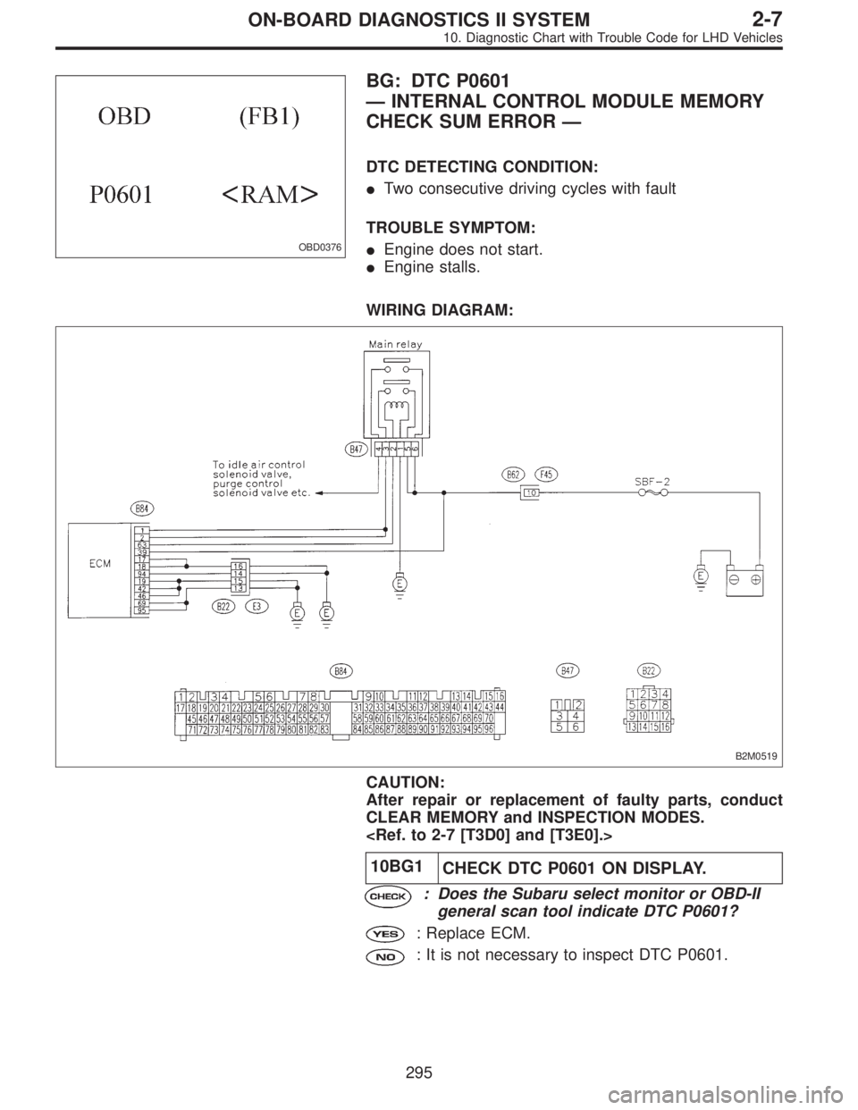
OBD0376
BG: DTC P0601
—INTERNAL CONTROL MODULE MEMORY
CHECK SUM ERROR—
DTC DETECTING CONDITION:
�Two consecutive driving cycles with fault
TROUBLE SYMPTOM:
�Engine does not start.
�Engine stalls.
WIRING DIAGRAM:
B2M0519
CAUTION:
After repair or replacement of faulty parts, conduct
CLEAR MEMORY and INSPECTION MODES.
10BG1
CHECK DTC P0601 ON DISPLAY.
: Does the Subaru select monitor or OBD-II
general scan tool indicate DTC P0601?
: Replace ECM.
: It is not necessary to inspect DTC P0601.
295
2-7ON-BOARD DIAGNOSTICS II SYSTEM
10. Diagnostic Chart with Trouble Code for LHD Vehicles
Page 2162 of 3342
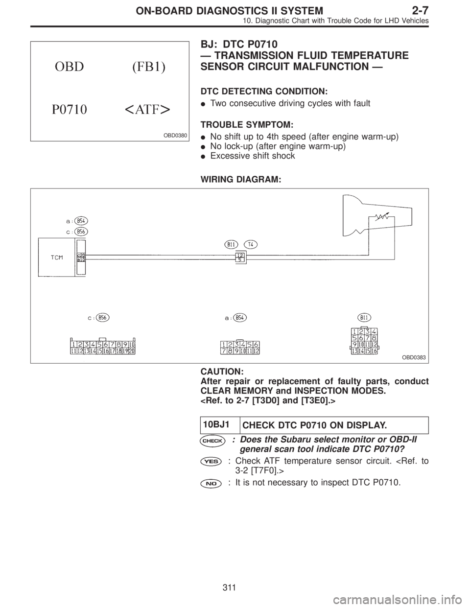
OBD0380
BJ: DTC P0710
—TRANSMISSION FLUID TEMPERATURE
SENSOR CIRCUIT MALFUNCTION—
DTC DETECTING CONDITION:
�Two consecutive driving cycles with fault
TROUBLE SYMPTOM:
�No shift up to 4th speed (after engine warm-up)
�No lock-up (after engine warm-up)
�Excessive shift shock
WIRING DIAGRAM:
OBD0383
CAUTION:
After repair or replacement of faulty parts, conduct
CLEAR MEMORY and INSPECTION MODES.
10BJ1
CHECK DTC P0710 ON DISPLAY.
: Does the Subaru select monitor or OBD-II
general scan tool indicate DTC P0710?
: Check ATF temperature sensor circuit.
3-2 [T7F0].>
: It is not necessary to inspect DTC P0710.
311
2-7ON-BOARD DIAGNOSTICS II SYSTEM
10. Diagnostic Chart with Trouble Code for LHD Vehicles
Page 2164 of 3342
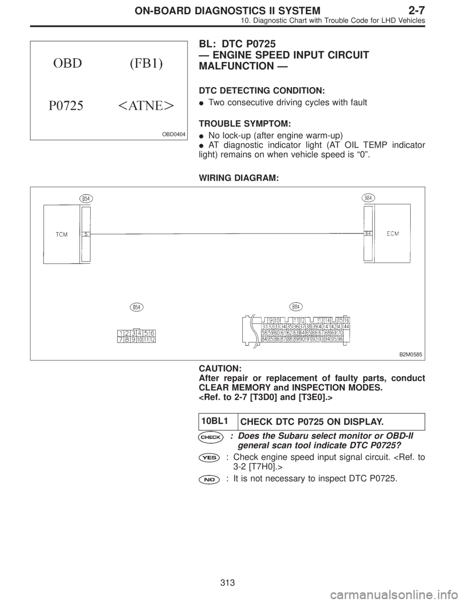
OBD0404
BL: DTC P0725
—ENGINE SPEED INPUT CIRCUIT
MALFUNCTION—
DTC DETECTING CONDITION:
�Two consecutive driving cycles with fault
TROUBLE SYMPTOM:
�No lock-up (after engine warm-up)
�AT diagnostic indicator light (AT OIL TEMP indicator
light) remains on when vehicle speed is“0”.
WIRING DIAGRAM:
B2M0585
CAUTION:
After repair or replacement of faulty parts, conduct
CLEAR MEMORY and INSPECTION MODES.
10BL1
CHECK DTC P0725 ON DISPLAY.
: Does the Subaru select monitor or OBD-II
general scan tool indicate DTC P0725?
: Check engine speed input signal circuit.
3-2 [T7H0].>
: It is not necessary to inspect DTC P0725.
313
2-7ON-BOARD DIAGNOSTICS II SYSTEM
10. Diagnostic Chart with Trouble Code for LHD Vehicles
Page 2167 of 3342
![SUBARU LEGACY 1997 Service Repair Manual 10BP2CHECK THROTTLE POSITION SENSOR
CIRCUIT.
Check throttle position sensor circuit. <Ref. to 3-2 [T7K0].>
: Is there any trouble in throttle position sen-
sor circuit?
: Repair or replace throttle po](/manual-img/17/57434/w960_57434-2166.png "SUBARU LEGACY 1997 Service Repair Manual 10BP2CHECK THROTTLE POSITION SENSOR
CIRCUIT.
Check throttle position sensor circuit. <Ref. to 3-2 [T7K0].>
: Is there any trouble in throttle position sen-
sor circuit?
: Repair or replace throttle po")
10BP2CHECK THROTTLE POSITION SENSOR
CIRCUIT.
Check throttle position sensor circuit.
: Is there any trouble in throttle position sen-
sor circuit?
: Repair or replace throttle position sensor circuit.
: Go to step10BP3.
10BP3CHECK VEHICLE SPEED SENSOR 1 CIR-
CUIT.
Check vehicle speed sensor 1 circuit.
: Is there any trouble in vehicle speed sensor
1 circuit?
: Repair or replace vehicle speed sensor 1 circuit.
: Go to step10BP4.
10BP4CHECK VEHICLE SPEED SENSOR 2 CIR-
CUIT.
Check vehicle speed sensor 2 circuit.
: Is there any trouble in vehicle speed sensor
2 circuit?
: Repair or replace vehicle speed sensor 2 circuit.
: Go to step10BP5.
10BP5
CHECK ENGINE SPEED INPUT CIRCUIT.
Check engine speed input circuit.
: Is there any trouble in engine speed input
circuit?
: Repair or replace engine speed input circuit.
: Go to next.
: Is there poor contact in TCM connector?
: Repair poor contact in TCM connector.
: Go to next.
: Is there any mechanical trouble in automatic
transmission?
: Repair or replace automatic transmission.
: Replace TCM.
316
2-7ON-BOARD DIAGNOSTICS II SYSTEM
10. Diagnostic Chart with Trouble Code for LHD Vehicles