Page 2302 of 3342

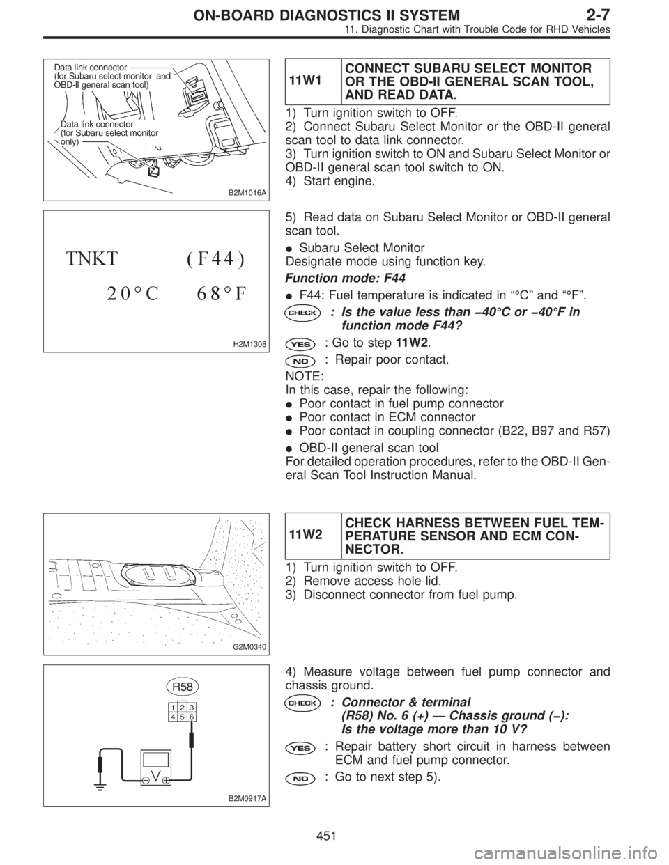
B2M1016A
11W1CONNECT SUBARU SELECT MONITOR
OR THE OBD-II GENERAL SCAN TOOL,
AND READ DATA.
1) Turn ignition switch to OFF.
2) Connect Subaru Select Monitor or the OBD-II general
scan tool to data link connector.
3) Turn ignition switch to ON and Subaru Select Monitor or
OBD-II general scan tool switch to ON.
4) Start engine.
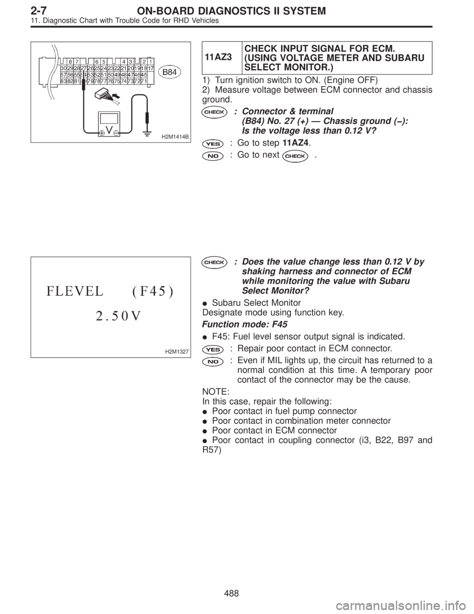
H2M1308
5) Read data on Subaru Select Monitor or OBD-II general
scan tool.
�Subaru Select Monitor
Designate mode using function key.
Function mode: F44
�F44: Fuel temperature is indicated in“°C”and“°F”.
: Is the value less than�40°Cor�40°Fin
function mode F44?
: Go to step11W2.
: Repair poor contact.
NOTE:
In this case, repair the following:
�Poor contact in fuel pump connector
�Poor contact in ECM connector
�Poor contact in coupling connector (B22, B97 and R57)
�OBD-II general scan tool
For detailed operation procedures, refer to the OBD-II Gen-
eral Scan Tool Instruction Manual.
G2M0340
11W2CHECK HARNESS BETWEEN FUEL TEM-
PERATURE SENSOR AND ECM CON-
NECTOR.
1) Turn ignition switch to OFF.
2) Remove access hole lid.
3) Disconnect connector from fuel pump.
B2M0917A
4) Measure voltage between fuel pump connector and
chassis ground.
: Connector & terminal
(R58) No. 6 (+)—Chassis ground (�):
Is the voltage more than 10 V?
: Repair battery short circuit in harness between
ECM and fuel pump connector.
: Go to next step 5).
451
2-7ON-BOARD DIAGNOSTICS II SYSTEM
11. Diagnostic Chart with Trouble Code for RHD Vehicles
Page 2339 of 3342

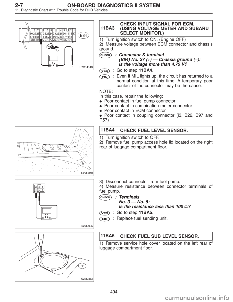
H2M1414B
11AZ3CHECK INPUT SIGNAL FOR ECM.
(USING VOLTAGE METER AND SUBARU
SELECT MONITOR.)
1) Turn ignition switch to ON. (Engine OFF)
2) Measure voltage between ECM connector and chassis
ground.
: Connector & terminal
(B84) No. 27 (+)—Chassis ground (�):
Is the voltage less than 0.12 V?
: Go to step11AZ4.
: Go to next.
H2M1327
: Does the value change less than 0.12 V by
shaking harness and connector of ECM
while monitoring the value with Subaru
Select Monitor?
�Subaru Select Monitor
Designate mode using function key.
Function mode: F45
�F45: Fuel level sensor output signal is indicated.
: Repair poor contact in ECM connector.
: Even if MIL lights up, the circuit has returned to a
normal condition at this time. A temporary poor
contact of the connector may be the cause.
NOTE:
In this case, repair the following:
�Poor contact in fuel pump connector
�Poor contact in combination meter connector
�Poor contact in ECM connector
�Poor contact in coupling connector (i3, B22, B97 and
R57)
488
2-7ON-BOARD DIAGNOSTICS II SYSTEM
11. Diagnostic Chart with Trouble Code for RHD Vehicles
Page 2345 of 3342

H2M1414B
11BA3CHECK INPUT SIGNAL FOR ECM.
(USING VOLTAGE METER AND SUBARU
SELECT MONITOR.)
1) Turn ignition switch to ON. (Engine OFF)
2) Measure voltage between ECM connector and chassis
ground.
: Connector & terminal
(B84) No. 27 (+)—Chassis ground (�):
Is the voltage more than 4.75 V?
: Go to step11BA4.
: Even if MIL lights up, the circuit has returned to a
normal condition at this time. A temporary poor
contact of the connector may be the cause.
NOTE:
In this case, repair the following:
�Poor contact in fuel pump connector
�Poor contact in combination meter connector
�Poor contact in ECM connector
�Poor contact in coupling connector (i3, B22, B97 and
R57)
G2M0340
11BA4
CHECK FUEL LEVEL SENSOR.
1) Turn ignition switch to OFF.
2) Remove fuel pump access hole lid located on the right
rear of luggage compartment floor.
B2M0935
3) Disconnect connector from fuel pump.
4) Measure resistance between connector terminals of
fuel pump.
: Terminals
No. 3—No. 5:
Is the resistance less than 100Ω?
: Go to step11BA5.
: Replace fuel sending unit.
G2M0863
11BA5
CHECK FUEL SUB LEVEL SENSOR.
1) Remove service hole cover located on the left rear of
luggage compartment floor.
494
2-7ON-BOARD DIAGNOSTICS II SYSTEM
11. Diagnostic Chart with Trouble Code for RHD Vehicles
Page 2358 of 3342
OBD0404
BL: DTC P0725
—ENGINE SPEED INPUT CIRCUIT
MALFUNCTION—
WIRING DIAGRAM:
B2M0585
NOTE:
Check engine speed signal input circuit.
507
2-7ON-BOARD DIAGNOSTICS II SYSTEM
11. Diagnostic Chart with Trouble Code for RHD Vehicles
Page 2371 of 3342
OBD0489
CA: DTC P1103
—ENGINE TORQUE CONTROL SIGNAL
CIRCUIT MALFUNCTION—
WIRING DIAGRAM:
B2M0598
NOTE:
Check engine torque control signal circuit.
520
2-7ON-BOARD DIAGNOSTICS II SYSTEM
11. Diagnostic Chart with Trouble Code for RHD Vehicles
Page 2407 of 3342
G3M0717
3. OPERATION OF SHIFT SELECTOR LEVER
WARNING:
Stop the engine while checking operation of selector
lever.
1) Check that selector lever does not move from“N”to“R”
without pushing the button.
2) Check that selector lever does not move from“R”to“P”
without pushing the button.
3) Check that selector lever does not move from“P”to“R”
without pushing the button.
4) Check that selector lever does not move from“3”to“2”
without pushing the button.
3
3-2AUTOMATIC TRANSMISSION AND DIFFERENTIAL
2. Pre-inspection
Page 2413 of 3342

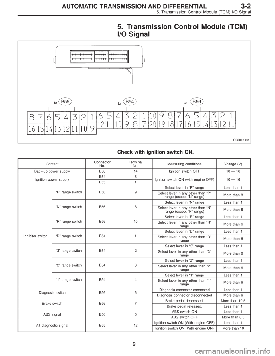
5. Transmission Control Module (TCM)
I/O Signal
OBD0093A
Check with ignition switch ON.
ContentConnector
No.Terminal
No.Measuring conditions Voltage (V)
Back-up power supply B56 14 Ignition switch OFF 10—16
Ignition power supplyB54 6
Ignition switch ON (with engine OFF) 10—16
B55 1
Inhibitor switch“P”range switch B56 9Select lever in“P”range Less than 1
Select lever in any other than“P”
range (except“N”range)More than 8
“N”range switch B56 8Select lever in“N”range Less than 1
Select lever in any other than“N”
range (except“P”range)More than 8
“R”range switch B56 10Select lever in“R”range Less than 1
Select lever in any other than“R”
rangeMore than 6
“D”range switch B54 1Select lever in“D”range Less than 1
Select lever in any other than“D”
rangeMore than 6
“3”range switch B54 2Select lever in“3”range Less than 1
Select lever in any other than“3”
rangeMore than 6
“2”range switch B54 3Select lever in“2”range Less than 1
Select lever in any other than“2”
rangeMore than 6
“1”range switch B54 4Select lever in“1”range Less than 1
Select lever in any other than“1”
rangeMore than 6
Diagnosis switch B56 6Diagnosis connector connected Less than 1
Diagnosis connector disconnected More than 6
Brake switch B56 7Brake pedal depressed. More than 10.5
Brake pedal released. Less than 1
ABS signal B56 5ABS switch ON Less than 1
ABS switch OFF More than 6.5
AT diagnostic signal B55 12Ignition switch ON (With engine OFF) Less than 1
Ignition switch ON (With engine ON) More than 10
9
3-2AUTOMATIC TRANSMISSION AND DIFFERENTIAL
5. Transmission Control Module (TCM) I/O Signal
Page 2416 of 3342
B: ABNORMAL DISPLAY ON AT OIL TEMP
INDICATOR
When any on-board diagnostic item is malfunctioning, the
display on the AT OIL TEMP indicator blinks immediately
after the engine starts.
The malfunctioning part or unit can be determined by a
trouble code during on-board diagnostic operation. Prob-
lems which occurred previously can also be identified
through the memory function.
If the AT OIL TEMP indicator does not show a problem
(although a problem is occurring), the problem can be
determined by checking the performance characteristics of
each sensor using the select monitor.
Indicator signal is as shown in the figure.
WARNING:
Warning can be noticed only when the engine is ini-
tially started.
B3M0410A
12
3-2AUTOMATIC TRANSMISSION AND DIFFERENTIAL
6. Diagnostic Chart for On-board Diagnostic System