Page 2452 of 3342

M: TROUBLE CODE 33
—VEHICLE SPEED SENSOR 2—
DIAGNOSIS:
�The vehicle speed signal is abnormal.
�The circuit in combination meter is faulty.
�The harness connector between TCM and vehicle speed
sensor is in short or open.
TROUBLE SYMPTOM:
�Erroneous idling
�Engine stalls.
�Poor driving performance
1. Check operation of speedometer.
OK
�Not OK
Check combination meter circuit.
2. Check harness connector between TCM and
combination meter.
OK
�Not OK
Repair or replace harness connector.
3. Check vehicle speed sensor 2.
OK
�Not OK
�Mechanical trouble between vehicle speed sensor
2 and speedometer shaft in transmission
�Failure of the vehicle speed sensor 2
,Replace vehicle speed sensor 2.
4. Check input signal for TCM.
OK
�Not OK
�Repair TCM connector terminal poor contact.
�Replace TCM.
When trouble code 33 reappears after clearing
memory, repair TCM connector terminal poor
contact.
B3M0640
�
�
�
�
48
3-2AUTOMATIC TRANSMISSION AND DIFFERENTIAL
7. Diagnostic Chart with Trouble Code
Page 2454 of 3342
 Install combination meter.
2) Connect connector to TCM.
3) Lift-up the vehicle and place safety stand.
CAUTION:
On AWD models, raise all wheels off floor.
4")
B3M0289
3. CHECK VEHICLE SPEED SENSOR 2.
1) Install combination meter.
2) Connect connector to TCM.
3) Lift-up the vehicle and place safety stand.
CAUTION:
On AWD models, raise all wheels off floor.
4) Disconnect connector from vehicle speed sensor 2.
5) Measure resistance between terminals of vehicle speed
sensor 2.
Terminals / Specified resistance:
(B17) No. 1—No. 2 / 350—450Ω
No. 1—Body/1MΩ, or more
No. 2—Body/1MΩ, or more
B3M0256
6) Push the TCS OFF switch to ON. (With TCS models)
7) Start the engine and set vehicle in 20 km/h (12 MPH)
condition.
8) Measure output signal of vehicle speed sensor 2.
WARNING:
Be careful not to be caught up by the running wheels.
9) Using a voltage meter; measure voltage between termi-
nals of vehicle speed sensor 2.
Terminals / Specified voltage:
(B17) No. 1—No. 2 / AC 2 V, or more
NOTE:
The speed difference between front and rear wheels may
light either the ABS or the ABS/TCS warning light, but this
indicates no malfunctions. When AT control diagnosis is
finished, perform the ABS or the ABS/TCS memory clear-
ance procedure of self-diagnosis system.
or 4-4d [T6D2] or [T9J0].>
50
3-2AUTOMATIC TRANSMISSION AND DIFFERENTIAL
7. Diagnostic Chart with Trouble Code
Page 2455 of 3342
 Install combination meter.
(2) Connect connector to TCM.
(3) Lift-up the vehicle and place safety stand.
WARNING:
On AWD models, make sure that all wheels are raised
o")
B3M0257
�Using oscilloscope:
(1) Install combination meter.
(2) Connect connector to TCM.
(3) Lift-up the vehicle and place safety stand.
WARNING:
On AWD models, make sure that all wheels are raised
off floor.
(4) Set oscilloscope to vehicle speed sensor 2.
Connector & terminal / No. 1—No. 2
B3M0254A
(5) Push the TCS OFF switch to ON. (With TCS mod-
els)
(6) Start the engine, and drive the wheels slowly.
(7) Measure signal voltage indicated on oscilloscope.
Specified voltage: AC 2 V, or more
NOTE:
The speed difference between front and rear wheels may
light either the ABS or the ABS/TCS warning light, but this
indicates no malfunctions. When AT control diagnosis is
finished, perform the ABS or the ABS/TCS memory clear-
ance procedure of self-diagnosis system.
or 4-4d [T6D2] or [T9J0].>
B3M0369A
4. CHECK INPUT SIGNAL FOR TCM.
1) Connect connector to vehicle speed sensor 2.
2) Lift-up the vehicle or set the vehicle on free roller.
CAUTION:
On AWD models, raise all wheels off floor.
3) Push the TCS OFF switch to ON. (With TCS models)
4) Start the engine, and drive the wheels slowly.
5) Measure voltage between TCM and body.
Connector & terminal / Specified voltage:
(B56) No. 11—Body / Less than 1↔
more than 9 V
NOTE:
The speed difference between front and rear wheels may
light either the ABS or the ABS/TCS warning light, but this
indicates no malfunctions. When AT control diagnosis is
finished, perform the ABS or the ABS/TCS memory clear-
ance procedure of self-diagnosis system.
or 4-4d [T6D2] or [T9J0].>
51
3-2AUTOMATIC TRANSMISSION AND DIFFERENTIAL
7. Diagnostic Chart with Trouble Code
Page 2461 of 3342
B3M0639
C: MODE F00—MODE DISPLAY—
SPECIFIED DATA:
Data at the left should be indicated.
Probable cause (if outside“specified data”)
1. Communication failure
(No communication method can be confirmed
with power ON.)
�(1)Check loose or poor connectors, or
shortcircuit.
(2) Check type of cartridge.
2. Vehicle types cannot be identified (due to
communication failure).�Check improper cartridge.
Replace with proper one.
G3M0724
D: MODE F01—BATTERY VOLTAGE (VB)—
CONDITION:
�Ignition switch ON
�Engine idling after warm-up
SPECIFIED DATA:
VB: 10—16 V
1. Battery�Check battery voltage and specific gravity of
electrolyte.
2. Charging system�(1)Measure regulating voltage under no loads.
(2) Check generator (as a single unit).
57
3-2AUTOMATIC TRANSMISSION AND DIFFERENTIAL
8. Diagnostic Chart with Select Monitor
Page 2463 of 3342
—
CONDITION:
Measure with engine operating at constant speed.
SPECIFIED DATA:
Same as tachometer reading (in combination meter)
Probable cause (if outside“")
G3M0727
G: MODE F06—ENGINE SPEED (EREV)—
CONDITION:
Measure with engine operating at constant speed.
SPECIFIED DATA:
Same as tachometer reading (in combination meter)
Probable cause (if outside“specified data”)
1. Conduct diagnostics in relation to MPFI
system for engine speed.
�OK
Check TCM and replace if necessary.
OBD0386
H: MODE F07
—ATF TEMPERATURE SENSOR (ATFT)—
F08 = ATF temperature (ATFT):
to be indicated in“deg C”.
CONDITION:
�Low ATF temperature (before engine/vehicle starts.)
�High ATF temperature (after driving vehicle for warm-
up.)
SPECIFIED DATA:
�Ambient temperature: ±50°F (±10°C)
(Low ATF temperature)
�ATF temperature: 158—230°F (70—11 0°C)
(High ATF temperature)
�Open harness: 176 deg F (80 deg C)
�Shorted harness: 320 deg F (160 deg C)
Probable cause (if outside“specified data”)
1. ATF temperature sensor
�Check performance characteristics of ATF
temperature sensor.
OK
Check TCM and replace if necessary.
�
59
3-2AUTOMATIC TRANSMISSION AND DIFFERENTIAL
8. Diagnostic Chart with Select Monitor
Page 2464 of 3342
—
CONDITION:
�Ignition switch ON (with engine OFF)
�Measure voltage while operating throttle valve from a
fully closed position to a fully open p")
B3M0383
I: MODE F09
—THROTTLE POSITION SENSOR (THV)—
CONDITION:
�Ignition switch ON (with engine OFF)
�Measure voltage while operating throttle valve from a
fully closed position to a fully open position.
SPECIFIED DATA:
�Fully closed position: 0.5±0.2 V
�Fully open position: 4.6±0.3 V
�From fully closed to fully open position:
Voltage must smoothly decrease.
�Open harness: 5.0±0.3 V
�Shorted harness: 0.00 V
Probable cause (if outside“specified data”)
1. Throttle position sensor
�Check performance characteristics of throttle
position sensor.
OK
Check TCM and replace if necessary.
G3M0730
J: MODE F10—GEAR POSITION (GEAR)—
CONDITION:
Check while driving vehicle (after warm-up).
SPECIFIED DATA:
Gear position (Refer to shift performance characteristics
chart.)
Probable cause (item outside“specified data”)
1. Shift solenoid 1
�Check performance characteristics of shift solenoid
1.
OK
2. Shift solenoid 2
�Check performance characteristics of shift solenoid
2.
OK
3. Shift solenoid 3
�Check performance characteristics of shift solenoid
3.
OK
Check TCM and replace as necessary.
�
�
�
�
60
3-2AUTOMATIC TRANSMISSION AND DIFFERENTIAL
8. Diagnostic Chart with Select Monitor
Page 2465 of 3342
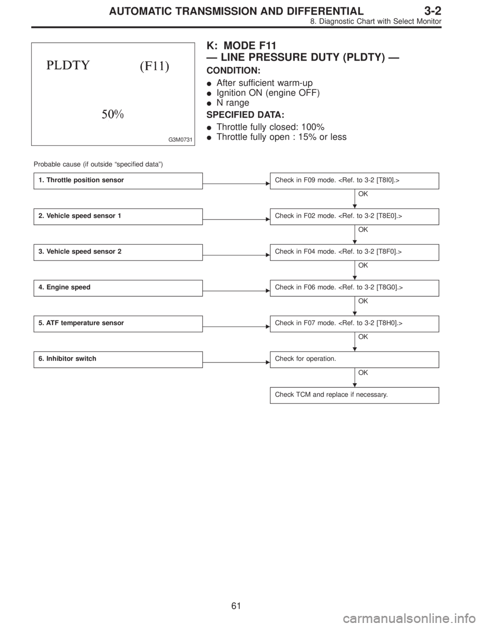
G3M0731
K: MODE F11
—LINE PRESSURE DUTY (PLDTY)—
CONDITION:
�After sufficient warm-up
�Ignition ON (engine OFF)
�N range
SPECIFIED DATA:
�Throttle fully closed: 100%
�Throttle fully open : 15% or less
Probable cause (if outside“specified data”)
1. Throttle position sensor
�Check in F09 mode.
OK
2. Vehicle speed sensor 1
�Check in F02 mode.
OK
3. Vehicle speed sensor 2
�Check in F04 mode.
OK
4. Engine speed
�Check in F06 mode.
OK
5. ATF temperature sensor
�Check in F07 mode.
OK
6. Inhibitor switch
�Check for operation.
OK
Check TCM and replace if necessary.
�
�
�
�
�
�
61
3-2AUTOMATIC TRANSMISSION AND DIFFERENTIAL
8. Diagnostic Chart with Select Monitor
Page 2466 of 3342
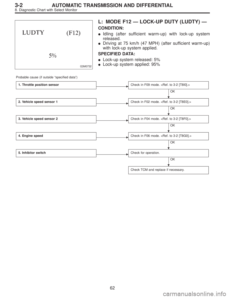
G3M0732
L: MODE F12—LOCK-UP DUTY (LUDTY)—
CONDITION:
�Idling (after sufficient warm-up) with lock-up system
released.
�Driving at 75 km/h (47 MPH) (after sufficient warm-up)
with lock-up system applied.
SPECIFIED DATA:
�Lock-up system released: 5%
�Lock-up system applied: 95%
Probable cause (if outside“specified data”)
1. Throttle position sensor
�Check in F09 mode.
OK
2. Vehicle speed sensor 1
�Check in F02 mode.
OK
3. Vehicle speed sensor 2
�Check in F04 mode.
OK
4. Engine speed
�Check in F06 mode.
OK
5. Inhibitor switch
�Check for operation.
OK
Check TCM and replace if necessary.
�
�
�
�
�
62
3-2AUTOMATIC TRANSMISSION AND DIFFERENTIAL
8. Diagnostic Chart with Select Monitor

1. Communication failure
(No communication method can be con")