Page 2536 of 3342

(P6) No. 14—body/2Vorless (AEC communi-
cation cable)
B4M0740A
4. CHECK OUTPUT VOLTAGE OF ENGINE CONTROL
MODULE.
1) Turn ignition switch OFF.
2) Connect engine control module.
3) Connect")
tion cable)
(P6) No. 14—body/2Vorless (AEC communi-
cation cable)
B4M0740A
4. CHECK OUTPUT VOLTAGE OF ENGINE CONTROL
MODULE.
1) Turn ignition switch OFF.
2) Connect engine control module.
3) Connect ABS/TCS control module.
4) Turn ignition switch ON.
5) Measure voltage between engine control module con-
nector and body.
Connector & terminal / Specified voltage:
(B84) No. 74—body / 4—5.4 V (AET communi-
cation cable)
(B84) No. 73—body / 4—5.4 V (AEB communi-
cation cable)
(B84) No. 47—body / 4—5.4 V (AEC communi-
cation cable)
B4M0438A
5. CHECK BODY SHORT OF HARNESS.
1) Turn ignition switch OFF.
2) Disconnect engine control module.
3) Disconnect ABS/TCS control module.
4) Measure resistance between ABS/TCS control module
connector and body.
Connector & terminal / Specified resistance:
(P6) No. 12—body/1MΩor more (AET commu-
nication cable)
(P6) No. 5—body/1MΩor more (AEB communi-
cation cable)
(P6) No. 14—body/1MΩor more (AEC commu-
nication cable)
60
4-4bBRAKES
8. Diagnostics Chart with Trouble Code
Page 2537 of 3342
B4M0728A
6. CHECK OPEN CIRCUIT OF HARNESS.
1) Turn ignition switch OFF.
2) Disconnect engine control module.
3) Disconnect ABS/TCS control module.
4) Measure resistance between ABS/TCS control module
connector and engine control module connector.
(P6) No. 12—(B84) No. 74 / 1Ωor less (AET commu-
nication
cable)
(P6) No. 5—(B84) No. 73 / 1Ωor less (AEB commu-
nication cable)
(P6) No. 14—(B84) No. 47 / 1Ωor less (AEC com-
munication
cable)
61
4-4bBRAKES
8. Diagnostics Chart with Trouble Code
Page 2554 of 3342
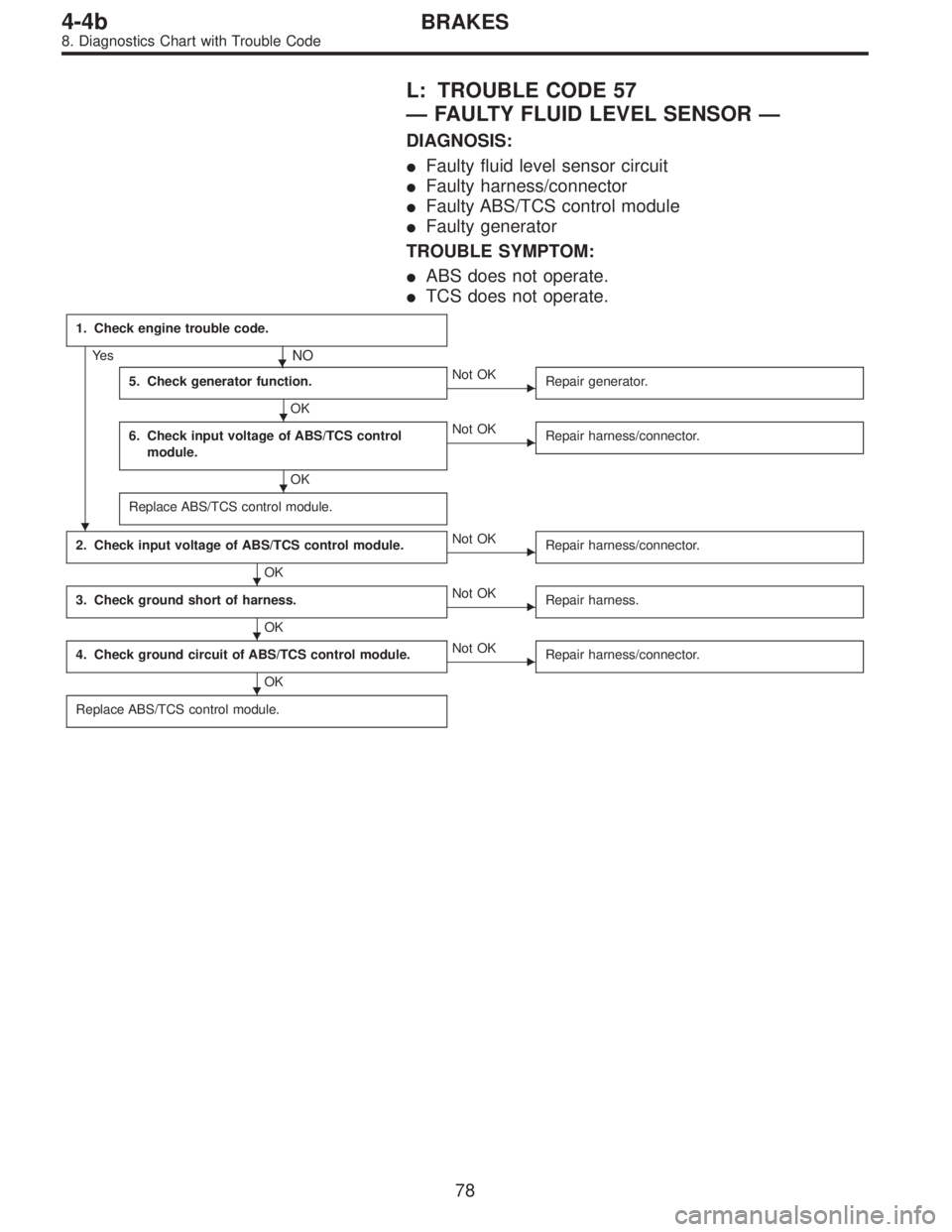
L: TROUBLE CODE 57
—FAULTY FLUID LEVEL SENSOR—
DIAGNOSIS:
�Faulty fluid level sensor circuit
�Faulty harness/connector
�Faulty ABS/TCS control module
�Faulty generator
TROUBLE SYMPTOM:
�ABS does not operate.
�TCS does not operate.
1. Check engine trouble code.
Ye s�NO
5. Check generator function.
OK
�Not OK
Repair generator.
6. Check input voltage of ABS/TCS control
module.
OK
�Not OK
Repair harness/connector.
Replace ABS/TCS control module.
2. Check input voltage of ABS/TCS control module.
OK
�Not OK
Repair harness/connector.
3. Check ground short of harness.
OK
�Not OK
Repair harness.
4. Check ground circuit of ABS/TCS control module.
OK
�Not OK
Repair harness/connector.
Replace ABS/TCS control module.
�
�
�
�
�
�
78
4-4bBRAKES
8. Diagnostics Chart with Trouble Code
Page 2555 of 3342
B4M0743
1. CHECK ENGINE TROUBLE CODE.
1) Read out engine trouble code.
2) Is trouble code 39 in memory?
B4M0395A
2. CHECK INPUT VOLTAGE OF ABS/TCS CONTROL
MODULE.
1) Turn ignition switch OFF.
2) Disconnect ABS/TCS control module connectors.
3) Turn ignition switch ON, while engine is idling.
4) Measure voltage between ABS/TCS control module
connector and body.
Connector & terminal / Specified voltage:
(P5) No. 1—body / 14.5±0.3 V
79
4-4bBRAKES
8. Diagnostics Chart with Trouble Code
Page 2556 of 3342
 Turn ignition switch OFF.
2) Remove No. 18 fuse from fuse and joint box.
3) Disconnect ABS/TCS control module connectors.
4) Measure resistance between AB")
B4M0733A
3. CHECK GROUND SHORT OF HARNESS.
1) Turn ignition switch OFF.
2) Remove No. 18 fuse from fuse and joint box.
3) Disconnect ABS/TCS control module connectors.
4) Measure resistance between ABS/TCS control module
connector and body.
Connector & terminal / Specified resistance:
(P5) No. 1—body/1MΩor more
B4M0405A
4. CHECK GROUND CIRCUIT OF ABS/TCS CONTROL
MODULE.
1) Turn ignition switch OFF.
2) Disconnect connector from ABS/TCS control module.
3) Measure resistance between ABS/TCS control module
connector and body.
Connector & terminal / Specified resistance:
(P4) No. 6—body / 1Ωor less
(P5) No. 5—body / 1Ωor less
(P7) No. 15—body / 1Ωor less
5. CHECK GENERATOR FUNCTION.
1) When the ignition key is at OFF, check the charge warn-
ing light is off.
2) Turn the key ON and ensure the light comes on.
3) Keep the engine running at idle and ensure the light
goes off.
B4M0473A
B4M0395A
6. CHECK INPUT VOLTAGE OF ABS/TCS CONTROL
MODULE.
1) Turn ignition switch OFF.
2) Disconnect ABS/TCS control module connectors.
3) Turn ignition switch ON.
4) Measure voltage between ABS/TCS control module
connector and body.
Connector & terminal / Specified voltage:
(P7) No. 20—body/2Vorless (Engine OFF)
(P7) No. 20—body / 10—14 V (Engine idling)
(P5) No. 1—body / 10—13 V (Engine OFF)
80
4-4bBRAKES
8. Diagnostics Chart with Trouble Code
Page 2589 of 3342

B4M0521
V: TROUBLE CODE 43
EGI LINE
—Faulty engine control module communication
cables—
DIAGNOSIS:
�AET communication cable is broken or short circuited.
�AEB communication cable is broken or short circuited.
�AEC communication cable is broken or short circuited.
�Faulty ABS/TCS control module
�Faulty engine control module
TROUBLE SYMPTOM:
�TCS does not operate.
1. Check communication cables.
OK
�
Terminal voltage
remains at 4—5.4 V.
Replace ABS/TCS control module.
�
Terminal voltage
remains at 10—14 V.
Go to step 2.
�
Terminal voltage
remains at2Vorless.
Go to step 4.
Replace ABS/TCS control module.
2. Check harness between ABS/TCS control
module and ECM.
OK
�Not OK
Repair harness.
3. Check ABS/TCS control module internal
circuits.
OK
�Not OK
Replace ABS/TCS control module.
Replace engine control module.
4. Check output voltage of ECM.
Not OK
�OK
6. Check open circuit of harness.
OK Not OK
Replace ABS/TCS
control module.
5. Check body short of harness.
OK
�Not OK
Repair harness/connector.
Replace engine control module.
�
�
�
�
��
�
11 3
4-4bBRAKES
10. Diagnostic Chart with Select Monitor
Page 2603 of 3342

11. General Diagnostics Table
��: Primary expected causes�: Secondary expected causes
Trouble conditions
SymptomsHydraulic
unit
Speed sensor
P valve
Master cylinder
Calipers and piston
Pad
Rotor
Hand brake
Piping
Mixture of air
Brake booster and check valve
Axle and wheel
Alignment
Play of pedal
Rough road surface
Semicylindrical road surface
Loose or worn suspension
Tire
Wrong connection and wiring
Stroke sensor Solenoid valve
Motor
Mount bush ABS function
Directional stability cannot be
obtained when braking.Vehicle turns to right or left.����������� ������������
Vehicle spins.�������������
Out-of-order brakesLong braking distance
��� ���������������
Brakes lock.������� � ��
Brakes drag.�����������������
Long pedal stroke� ���� �����
Abnormal vehicle pitching�� ������
Unstable braking force. One-
side brake refuses to work.����������� ����������
TCS function
When accelerating abruptly,
directional stability cannot be
obtained when traveling on a
slippery road surface.Vehicle moves unsteadily.������������������
Handle refuses to work.�������������
Handle loses control.���������� ���������
Bad acceleration, engine stall-
ing (In addition to the causes
listed here, check the ECM
specifications.)Engine stalls. Engine speed
fails to increase.�����������
Engine speed increases sud-
denly.��������������������
Vibration occurs and abnormal
noise is produced.
�When applying brakes abruptly.
�When accelerating abruptly.
�When driving on a slippery
road surface.Brake pedal heavily vibrates
when applying brakes.
�� � � �������
Loud hydraulic unit operating
noise��������
Noise is produced from front
of vehicle.���������������������
Noise is produced from rear of
vehicle.����������������
NOTE:
This list includes no engine failure and transmission failure.
127
4-4bBRAKES
11. General Diagnostics Table
Page 2604 of 3342
 and,
when it operates, acceleration can become slow*. T")
12. Phenomena Peculiar to the System
1. WHEN TRAVELING WITH EXTREMELY UNDER
INFLATED TIRES
The TCS is apt to operate (particularly when turning) and,
when it operates, acceleration can become slow*. This
state is not abnormal. Immediately restore the tires to nor-
mal by traveling after releasing the TCS with the TCS OFF
switch.
* Poor acceleration is sometimes caused by the engine
itself. Check whether or not the TCS operating indicator
light (green) comes on to determine that the failure is
caused by the TCS control.
2. WHEN THE T TIRES ARE FITTED
The TCS is apt to operate (particularly when turning) and,
when it operates, acceleration can become slow. This state
is not abnormal. Immediately restore the tires to normal by
traveling after releasing the TCS with the TCS OFF switch.
3. WHEN OPERATING THE TCS CONTINUOUSLY ON
A SLOPE IMPOSSIBLE TO CLIMB OR IN STACK
S TAT E
When operating the TCS for a long time, it can be auto-
matically turned off (the OFF indicator light will come on),
stopping braking. This state is not abnormal. It automati-
cally resets by stopping and leaving the vehicle.
4. WHEN HEAVY LOAD IS PLACED ON THE BRAKES
If service brakes are used too often when descending a
long slope, heavy load can be placed on the brakes. To
prevent this problem, the TCS is automatically turned off
(the OFF indicator light will come on). This state is not
abnormal. Stop the vehicle and leave it in the same way as
step 3, it automatically resets.
5. KICKBACK TO THE BRAKE PEDAL WHEN THE
ABS IS OPERATING
Compared with ABS of the AWD model system, pedal kick-
back with large amplitude of vibration and long cycle can
be felt. This is caused by the difference in system configu-
ration and, therefore, not abnormal. If you receive an
inquiry from your clients, fully explain this point.
128
4-4bBRAKES
12. Phenomena Peculiar to the System
 Turn ignition switch OFF.
2) Disconnect engine control module.
3) Disconnect ABS/TCS control module.
4) Measure resistance between ABS/TCS control module")
 Read out engine trouble code.
2) Is trouble code 39 in memory?
B4M0395A
2. CHECK INPUT VOLTAGE OF ABS/TCS CONTROL
MODULE.
1) Turn ignition switch OFF.
2) Disco")