Page 2500 of 3342
D: ABS WARNING LIGHT ONLY REMAINS
ILLUMINATED.
—WHEN STARTING THE ENGINE, NEITHER
TCS WARNING, TCS OFF INDICATOR NOR
TCS OPERATING INDICATOR LIGHT COMES
ON EVEN ONCE, AND ABS WARNING LIGHT
AND MALFUNCTION INDICATOR LAMP
ILLUMINATE.—
1. Check input voltage of ABS/TCS control mod-
ule.
OK
�Not OK
Repair harness/connector.
Replace ABS/TCS control module.
B4M0394
�
24
4-4bBRAKES
7. Diagnostics Chart for Warning Light Circuit Failure
Page 2502 of 3342
E: TCS OFF INDICATOR LIGHT DOES NOT
GO OFF.
—ABS WARNING, TCS WARNING AND TCS
OPERATING INDICATOR LIGHTS COME ON
AND GO OFF PROPERLY WHEN STARTING
THE ENGINE, BUT TCS OFF INDICATOR
DOES NOT GO OFF FOR MORE THAN 30
SECONDS AFTER ENGINE RUNNING.—
Does malfunction indicator lamp (Check engine
lamp) come on?
No
�Ye s
Conduct OBD II diagnosis.
1. Check harness connector between ABS/TCS
control module and TCS OFF indicator light.
OK
�Not OK
Repair harness/connector.
Replace ABS/TCS control module.
B4M0396
�
�
26
4-4bBRAKES
7. Diagnostics Chart for Warning Light Circuit Failure
Page 2504 of 3342
F: TCS OPERATING INDICATOR LIGHT DOES
NOT GO OFF.
—WHEN STARTING THE ENGINE, ABS
WARNING, TCS WARNING AND TCS OFF
INDICATOR LIGHTS COME ON AND GO OFF
PROPERLY BUT TCS OPERATING
INDICATOR LIGHT ONLY KEEPS ON.—
1. Check harness connector between ABS/TCS
control module and TCS operating indicator
light.
OK
�Not OK
Repair harness/connector.
Replace ABS/TCS control module.
B4M0398
�
28
4-4bBRAKES
7. Diagnostics Chart for Warning Light Circuit Failure
Page 2506 of 3342
G: TCS OFF SWITCH DOES NOT FUNCTION.
—TCS OFF INDICATOR LIGHT COMES ON
AND GOES OFF PROPERLY WHEN
STARTING THE ENGINE, WHILE THIS LIGHT
NEITHER COMES ON NOR GOES OFF WHEN
PUSHING THE TCS OFF SWITCH.—
1. Check TCS OFF switch
OK
�Not OK
Replace TCS OFF switch.
2. Check harness connector between ABS/TCS
control module and TCS OFF switch.
OK
�Not OK
Repair harness/connector.
Replace ABS/TCS control module.
B4M0535
�
�
30
4-4bBRAKES
7. Diagnostics Chart for Warning Light Circuit Failure
Page 2521 of 3342
5. CHECK SOURCES OF SIGNAL NOISE.
1) Check that the mobile phone, personal radio and other
wireless apparatus are correctly installed.
2) Check that the antenna and other possible noise
sources are distant enough from the sensor harness.
3) Check that the sealed wires of the front harness sensor
(in the engine room) are securely grounded.
4) Check that between ABS/TCS control module and the
rear sensor harness has the correct twist pitch.
Twist pitch:
25 mm (0.98 in) or less
6. CHECK HYDRAULIC UNIT OPERATIONS.
1) Operate the ABS sequence control and check that the
brake fluid pressure at the malfunctioning brake line
increases and decreases properly.
45
4-4bBRAKES
8. Diagnostics Chart with Trouble Code
Page 2532 of 3342
B4M0430
1. CHECK GENERATOR.
1) Idling after warm-up.
2) Measure voltage between generator B terminal and
body.
Connector / Specified voltage:
(F25)—body / 10—15 V
2. CHECK BATTERY TERMINAL.
Check that the positive and negative battery terminals are
firmly fixed.
B4M0431A
3. CHECK INPUT VOLTAGE OF ABS/TCS CONTROL
MODULE.
1) Turn ignition switch OFF.
2) Disconnect connector from ABS/TCS control module.
3) Run the engine at idle.
4) Measure voltage between ABS/TCS control module
connector and body.
Connector & terminal / Specified voltage:
(P5) No. 1—body / 10—15 V
B4M0405A
4. CHECK GROUND CIRCUIT OF ABS/TCS CONTROL
MODULE.
1) Turn ignition switch OFF.
2) Disconnect connector from ABS/TCS control module.
3) Measure resistance between ABS/TCS control module
connector and body.
Connector & terminal / Specified resistance:
(P4) No. 6—body / 1Ωor less
(P5) No. 5—body / 1Ωor less
(P7) No. 15—body / 1Ωor less
56
4-4bBRAKES
8. Diagnostics Chart with Trouble Code
Page 2533 of 3342

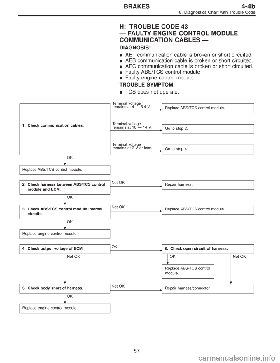
H: TROUBLE CODE 43
—FAULTY ENGINE CONTROL MODULE
COMMUNICATION CABLES—
DIAGNOSIS:
�AET communication cable is broken or short circuited.
�AEB communication cable is broken or short circuited.
�AEC communication cable is broken or short circuited.
�Faulty ABS/TCS control module
�Faulty engine control module
TROUBLE SYMPTOM:
�TCS does not operate.
1. Check communication cables.
OK
�
Terminal voltage
remains at 4—5.4 V.
Replace ABS/TCS control module.
�
Terminal voltage
remains at 10—14 V.
Go to step 2.
�
Terminal voltage
remains at2Vorless.
Go to step 4.
Replace ABS/TCS control module.
2. Check harness between ABS/TCS control
module and ECM.
OK
�Not OK
Repair harness.
3. Check ABS/TCS control module internal
circuits.
OK
�Not OK
Replace ABS/TCS control module.
Replace engine control module.
4. Check output voltage of ECM.
Not OK
�OK
6. Check open circuit of harness.
OK Not OK
Replace ABS/TCS control
module.
5. Check body short of harness.
OK
�Not OK
Repair harness/connector.
Replace engine control module.
�
�
�
�
��
�
57
4-4bBRAKES
8. Diagnostics Chart with Trouble Code
Page 2535 of 3342

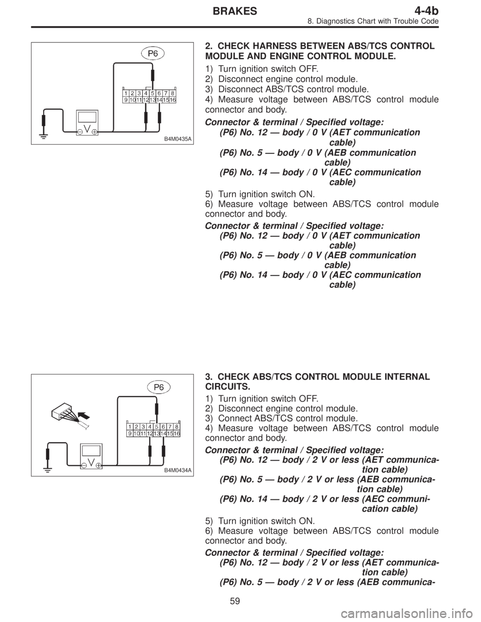
B4M0435A
2. CHECK HARNESS BETWEEN ABS/TCS CONTROL
MODULE AND ENGINE CONTROL MODULE.
1) Turn ignition switch OFF.
2) Disconnect engine control module.
3) Disconnect ABS/TCS control module.
4) Measure voltage between ABS/TCS control module
connector and body.
Connector & terminal / Specified voltage:
(P6) No. 12—body/0V(AET communication
cable)
(P6) No. 5—body/0V(AEB communication
cable)
(P6) No. 14—body/0V(AEC communication
cable)
5) Turn ignition switch ON.
6) Measure voltage between ABS/TCS control module
connector and body.
Connector & terminal / Specified voltage:
(P6) No. 12—body/0V(AET communication
cable)
(P6) No. 5—body/0V(AEB communication
cable)
(P6) No. 14—body/0V(AEC communication
cable)
B4M0434A
3. CHECK ABS/TCS CONTROL MODULE INTERNAL
CIRCUITS.
1) Turn ignition switch OFF.
2) Disconnect engine control module.
3) Connect ABS/TCS control module.
4) Measure voltage between ABS/TCS control module
connector and body.
Connector & terminal / Specified voltage:
(P6) No. 12—body/2Vorless (AET communica-
tion cable)
(P6) No. 5—body/2Vorless (AEB communica-
tion cable)
(P6) No. 14—body/2Vorless (AEC communi-
cation cable)
5) Turn ignition switch ON.
6) Measure voltage between ABS/TCS control module
connector and body.
Connector & terminal / Specified voltage:
(P6) No. 12—body/2Vorless (AET communica-
tion cable)
(P6) No. 5—body/2Vorless (AEB communica-
59
4-4bBRAKES
8. Diagnostics Chart with Trouble Code