Page 2467 of 3342
G3M0733
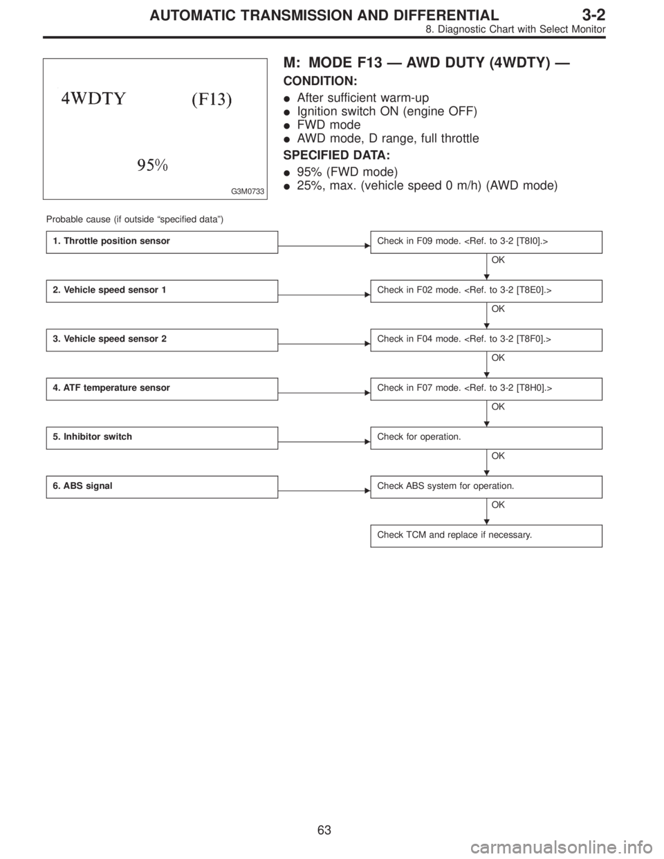
M: MODE F13—AWD DUTY (4WDTY)—
CONDITION:
�After sufficient warm-up
�Ignition switch ON (engine OFF)
�FWD mode
�AWD mode, D range, full throttle
SPECIFIED DATA:
�95% (FWD mode)
�25%, max. (vehicle speed 0 m/h) (AWD mode)
Probable cause (if outside“specified data”)
1. Throttle position sensor
�Check in F09 mode.
OK
2. Vehicle speed sensor 1
�Check in F02 mode.
OK
3. Vehicle speed sensor 2
�Check in F04 mode.
OK
4. ATF temperature sensor
�Check in F07 mode.
OK
5. Inhibitor switch
�Check for operation.
OK
6. ABS signal
�Check ABS system for operation.
OK
Check TCM and replace if necessary.
�
�
�
�
�
�
63
3-2AUTOMATIC TRANSMISSION AND DIFFERENTIAL
8. Diagnostic Chart with Select Monitor
Page 2468 of 3342
B3M0259
N: MODE F14
—THROTTLE POSITION SENSOR POWER
SUPPLY (THVCC)—
CONDITION:
Ignition switch ON (engine OFF)
SPECIFIED DATA:
5.12±0.1 V
Probable cause (Item outside“specified data”)
1. Throttle position sensor power supply
�Check throttle sensor line.
OK
Check TCM and replace if necessary.
B3M0370
O: MODE F15
—MASS AIR FLOW SIGNAL (AFM)—
CONDITION:
�Ignition switch ON (engine ON)
�N range
�Idling
SPECIFIED DATA:
Engine warm-up: 0.5—1.22 V
Probable cause (if outside“specified data”)
1. Mass air flow signal
�Check performance characteristics of mass air flow
signal.
OK
Check TCM and replace if necessary.
�
�
64
3-2AUTOMATIC TRANSMISSION AND DIFFERENTIAL
8. Diagnostic Chart with Select Monitor
Page 2471 of 3342
 Turn ignition switch OFF.
2) Disconnect connector from TCM.
3) Measure resistance of harness connector between
TCM and diagnosi")
B3M0373A
1. CHECK HARNESS CONNECTOR BETWEEN TCM
AND DIAGNOSIS SWITCH.
1) Turn ignition switch OFF.
2) Disconnect connector from TCM.
3) Measure resistance of harness connector between
TCM and diagnosis switch.
Connector & terminal / Specified resistance:
(B56) No. 6—(B82) No.5/1Ω, or less.
B3M0273B
4) Measure resistance of harness connector between
TCM and body to make sure that circuit does not short.
Connector & terminal / Specified resistance:
(B56) No.6—Body / 1 MΩ, or more
B3M0271B
2. CHECK INPUT SIGNAL FOR TCM.
1) Connect connector to TCM.
2) Turn ignition switch ON (with engine OFF).
3) Measure signal voltage for TCM while connecting and
disconnecting the diagnosis terminal to diagnosis connec-
tor.
Connector & terminal / Specified voltage:
(B56) No. 6—Body / Less than 1 V (Connected)
More than 6 V (Discon-
nected)
B4M0387A
3. CHECK DIAGNOSIS SWITCH GROUND LINE.
Measure resistance of harness terminal between diagnosis
terminal and body.
Connector & terminal / Specified resistance:
(B81)—Body / 1Ω, or less
67
3-2AUTOMATIC TRANSMISSION AND DIFFERENTIAL
8. Diagnostic Chart with Select Monitor
Page 2490 of 3342

B: CHECK LIST FOR INTERVIEW
Check the following items about the vehicle’s state.
1. THE STATE OF THE WARNING LIGHTS
a. ABS warning light
�
1Is always on.�2Sometimes comes on.�3Comes on only once.�4Does not come on.
When/how long does it come on?
Ignition key
position�
1Lock�2Acc�3On (before starting engine)�4Start�5On after starting (Engine: run)
�6On after starting (Engine: stop)
Timing�
1Immediately after ignition is on.�2Immediately after ignition starts.
�3When advancing (Speedmiles/h,miles/h)�4While traveling at a constant speed (Speedmiles/h)
�5When decelerating (Speedmiles/h,miles/h)
�6When turning (To right, to left, steering angledeg., steering timesec)
�7When other electrical parts move (Part name:, Operating condition)
�8When moving other electrical parts (Part name:, Operating condition)
b. TCS warning light
�
1Is always on.�2Sometimes comes on.�3Comes on only once.�4Does not come on.
When does it come on?
Ignition key
position�
1Lock�2Acc�3On (before starting engine)�4Start�5On after starting (Engine: run)
�6On after starting (Engine: stop)
Timing�
1Immediately after ignition is on.�2Immediately after ignition starts.
�3When advancing (Speedmiles/h,miles/h)�4While traveling at a constant speed (Speedmiles/h)
�5When decelerating (Speedmiles/h,miles/h)
�6When turning (To right, to left, steering angledeg., steering timesec)
�7When other electrical parts move (Part name:, Operating condition)
�8When moving other electrical parts (Part name:, Operating condition)
c. TCS OFF indicator light
�
1Is always on.�2Sometimes comes on.�3Comes on only once.�4Does not come on.
When/how long does it come on?
Ignition key
position�
1Lock�2Acc�3On (before starting engine)�4Start�5On after starting (Engine: run)
�6On after starting (Engine: stop)
Timing�
1Immediately after ignition is on.�2Immediately after ignition starts.
�3When advancing (Speedmiles/h,miles/h)�4While traveling at a constant speed (Speedmiles/h)
�5When decelerating (Speedmiles/h,miles/h)
�6When turning (To right, to left, steering angledeg., steering timesec)
�7When other electrical parts move (Part name:, Operating condition)
�8When moving other electrical parts (Part name:, Operating condition)
d. TCS operation indicator light
�
1Is always on.�2Sometimes comes on.�3Comes on only once.�4Does not come on.
When does it come on?
Ignition key
position�
1Lock�2Acc�3On (before starting engine)�4Start�5On after starting (Engine: run)
�6On after starting (Engine: stop)
Timing�
1Immediately after ignition is on.�2Immediately after ignition starts.
�3When advancing (Speedmiles/h,miles/h)�4While traveling at a constant speed (Speedmiles/h)
�5When decelerating (Speedmiles/h,miles/h)
�6When turning (To right, to left, steering angledeg., steering timesec)
�7When other electrical parts move (Part name:, Operating condition)
�8When moving other electrical parts (Part name:, Operating condition)
14
4-4bBRAKES
6. Diagnostics Chart for On-board Diagnosis System
Page 2494 of 3342
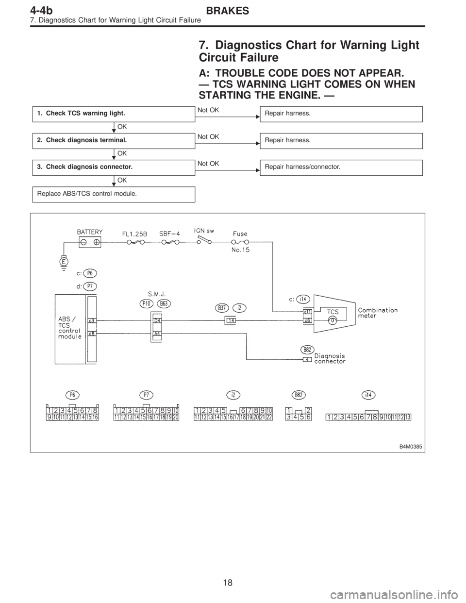
7. Diagnostics Chart for Warning Light
Circuit Failure
A: TROUBLE CODE DOES NOT APPEAR.
—TCS WARNING LIGHT COMES ON WHEN
STARTING THE ENGINE.—
1. Check TCS warning light.
OK
�Not OK
Repair harness.
2. Check diagnosis terminal.
OK
�Not OK
Repair harness.
3. Check diagnosis connector.
OK
�Not OK
Repair harness/connector.
Replace ABS/TCS control module.
B4M0385
�
�
�
18
4-4bBRAKES
7. Diagnostics Chart for Warning Light Circuit Failure
Page 2496 of 3342
B: ABS AND TCS WARNING LIGHT DO NOT
GO OFF.
—TCS OFF AND TCS OPERATING
INDICATOR LIGHTS COME ON AND GO OFF
PROPERLY WHEN STARTING THE ENGINE,
WHILE ABS WARNING AND TCS WARNING
LIGHTS KEEP ON.—
1. Check brake fluid level.
OK
�Not OK
Add to brake fluid.
2. Check brake fluid level sensor.
OK
�Not OK
Replace master cylinder.
3. Check harness connector between ABS/TCS
control module and alternator.
OK
�Not OK
Replace harness connector.
Replace ABS/TCS control module.
B4M0389
�
�
�
20
4-4bBRAKES
7. Diagnostics Chart for Warning Light Circuit Failure
Page 2497 of 3342
1. CHECK BRAKE FLUID LEVEL.
Check that brake fluid level is above the MIN indication on
the reservoir tank.
B4M0716A
2. CHECK BRAKE FLUID LEVEL SENSOR.
1) Turn ignition switch OFF.
2) Disconnect connector from brake fluid level sensor.
Connector & terminal / Specified resistance:
(B16) No. 1—No.2/0Ω(Leaving float where it
is.)
(B16) No. 1—No.2/1MΩ(When pushing float
down.)
B4M0717A
3. CHECK HARNESS CONNECTOR BETWEEN ABS/
TCS CONTROL MODULE AND ALTERNATOR.
1) Turn ignition switch OFF.
2) Connect connector from brake fluid level sensor.
3) Disconnect all connectors from ABS/TCS control mod-
ule.
4) Measure voltage between ABS/TCS control module
connector and body.
Connector & terminal / Specified voltage:
(P7) No. 20—body/2Vorless
5) Start the engine.
6) Measure voltage between ABS/TCS control module
connector and body.
Connector & terminal / Specified voltage:
(P7) No. 20—body / 10—14 V
21
4-4bBRAKES
7. Diagnostics Chart for Warning Light Circuit Failure
Page 2498 of 3342
C: TCS WARNING LIGHT AND TCS
INDICATOR OFF AND TCS OPERATING
INDICATOR LIGHTS COME ON AND GO OFF
PROPERLY, WHILE ABS WARNING LIGHT
DOES NOT GO OFF.
—TCS WARNING LIGHT AND TCS OFF
INDICATOR AND TCS OPERATING
INDICATOR LIGHTS COME ON AND GO OFF
PROPERLY WHEN STARTING THE ENGINE,
WHILE ABS WARNING LIGHT DOES NOT GO
OFF.—
1. Check harness connector between ABS/TCS
control module and ABS warning light.�Repair harness connector.
Replace ABS/TCS control module.
B4M0392
�
22
4-4bBRAKES
7. Diagnostics Chart for Warning Light Circuit Failure
—
CONDITION:
Ignition switch ON (engine OFF)
SPECIFIED DATA:
5.12±0.1 V
Probable cause (Item outside“specified data”)
1. Thro")

 Turn ignition switch OFF.
2) Disconnect conne")
