Page 2436 of 3342
 Turn ignition switch ON (with engine OFF) and measure
signal voltage input of TCM.
2) Start and warm-up the engine. Measure signal voltage
input of TCM.
Conn")
OBD0384A
3. CHECK INPUT SIGNAL FOR TCM.
1) Turn ignition switch ON (with engine OFF) and measure
signal voltage input of TCM.
2) Start and warm-up the engine. Measure signal voltage
input of TCM.
Connector & terminal / Specified voltage:
(B54) No. 10—(B56) No. 20 /
3.45±0.55 V [ATF temperature: 20°C (68°F)]
1.2±0.2 V [ATF temperature: 80°C (176°F)]
OBD0145A
�Using Subaru select monitor:
(1) Turn ignition switch to OFF.
(2) Connect the Subaru select monitor to data link con-
nector.
(3) Turn ignition switch to ON and Subaru select moni-
tor switch to ON.
OBD0386
OBD0387
(4) Start and warm-up the engine.
(5) Read data on Subaru select monitor.
(6) Designate mode using function key.
Function mode: F07 or F08
SPECIFIED DATA:
F07:�Ambient temperature: ±50 deg F
�ATF temperature: 158—230 deg F
�Open harness: 176 deg F
�Shorted harness: 320 deg F
F08:�Ambient temperature: ±10 deg C
�ATF temperature: 70—110 deg C
�Open harness: 80 deg C
�Shorted harness: 160 deg C
�F07: ATF temperature is indicated in“deg F”.
�F08: ATF temperature is indicated in“deg C”.
32
3-2AUTOMATIC TRANSMISSION AND DIFFERENTIAL
7. Diagnostic Chart with Trouble Code
Page 2437 of 3342
G: TROUBLE CODE 22
—MASS AIR FLOW SIGNAL—
DIAGNOSIS:
Input signal circuit of TCM from ECM is open or shorted.
1. Check trouble code on engine side.
[T10B0], [T11B0].>
OK
�Not OK
Check for cause of trouble in engine.
2. Check harness connector between TCM and
ECM.
OK
�Not OK
Repair TCM connector terminal poor contact.
3. Check input signal for TCM.
OK
�Not OK
�Replace TCM.
Clear memory,Confirmation test,Not OK,
Repair TCM connector terminal poor contact.
B3M0475
1. CHECK TROUBLE CODE ON ENGINE SIDE.
Using Subaru select monitor or OBD-general scan tool,
check trouble code of mass air flow sensor on engine side.
�
�
�
33
3-2AUTOMATIC TRANSMISSION AND DIFFERENTIAL
7. Diagnostic Chart with Trouble Code
Page 2438 of 3342
 Turn ignition switch to OFF.
2) Disconnect connectors from TCM and ECM.
3) Measure resistance of harness connector between
TCM and ECM.
Conn")
B3M0476A
2. CHECK HARNESS CONNECTOR BETWEEN TCM
AND ECM.
1) Turn ignition switch to OFF.
2) Disconnect connectors from TCM and ECM.
3) Measure resistance of harness connector between
TCM and ECM.
Connector & terminal / Specified resistance:
(B54) No. 9—(B84) No. 47 / 1Ω, or less
B3M0224B
4) Measure resistance of harness connector between
TCM and body to make sure that circuit does not short.
Connector & terminal / Specified resistance:
(B54) No. 9—Body/1MΩ, or more
B3M0222B
3. CHECK INPUT SIGNAL FOR TCM.
1) Connect connectors to TCM and ECM.
2) Start the engine. (engine idling after warm-up)
3) Measure signal voltage between TCM connector termi-
nal and body.
Connector & terminal / Specified voltage:
Engine warm-up;
(B54) No. 9—Body / 0.5—1.22 V
OBD0145A
�Using Subaru select monitor:
(1) Connect connectors to TCM and ECM.
(2) Turn ignition switch to OFF.
(3) Connect the Subaru select monitor to data link con-
nector.
(4) Turn ignition switch to ON and Subaru select moni-
tor switch to ON.
(5) Start and warm-up the engine.
B3M0370
(6) Read data on Subaru select monitor.
(7) Designate mode using function key.
Function mode: F15
SPECIFIED DATA:
0.5—1.22 V (Engine warm-up)
34
3-2AUTOMATIC TRANSMISSION AND DIFFERENTIAL
7. Diagnostic Chart with Trouble Code
Page 2439 of 3342
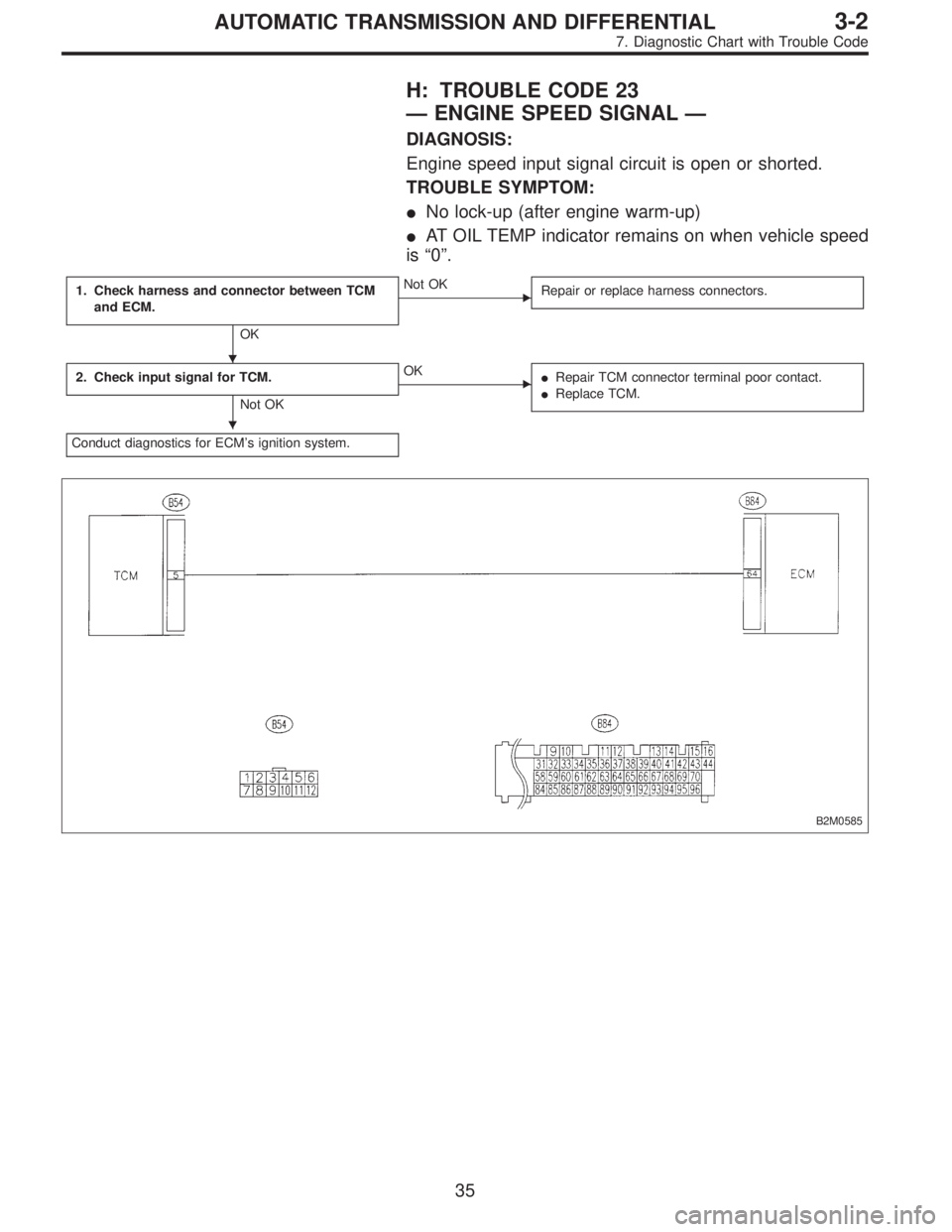
H: TROUBLE CODE 23
—ENGINE SPEED SIGNAL—
DIAGNOSIS:
Engine speed input signal circuit is open or shorted.
TROUBLE SYMPTOM:
�No lock-up (after engine warm-up)
�AT OIL TEMP indicator remains on when vehicle speed
is“0”.
1. Check harness and connector between TCM
and ECM.
OK
�Not OK
Repair or replace harness connectors.
2. Check input signal for TCM.
Not OK
�OK
�Repair TCM connector terminal poor contact.
�Replace TCM.
Conduct diagnostics for ECM’s ignition system.
B2M0585
�
�
35
3-2AUTOMATIC TRANSMISSION AND DIFFERENTIAL
7. Diagnostic Chart with Trouble Code
Page 2440 of 3342
 Turn ignition switch to OFF.
2) Disconnect connectors from TCM and ECM.
3) Measure resistance of harness connector between
TCM and ECM.")
B3M0477A
1. CHECK HARNESS AND CONNECTOR BETWEEN
TCM AND ECM.
1) Turn ignition switch to OFF.
2) Disconnect connectors from TCM and ECM.
3) Measure resistance of harness connector between
TCM and ECM.
Connector & terminal / Specified resistance:
(B54) No. 5—(B84) No. 64 / 1Ω, or less
OBD0410A
4) Measure resistance of harness connector between
TCM and body to make sure that circuit does not short.
Connector & terminal / Specified resistance:
(B54) No. 5—Body/1MΩ, or more
OBD0406A
2. CHECK INPUT SIGNAL FOR TCM.
1) Connect connectors to ECM and TCM.
2) Turn ignition switch ON (with engine OFF).
3) Measure signal voltage for TCM.
Connector & terminal / Specified voltage:
(B54) No. 5—Body / 10.5 V, or more
OBD0145A
�Using Subaru select monitor:
(1) Connect connectors to ECM and TCM.
(2) Turn ignition switch to OFF.
(3) Connect the Subaru select monitor to data link con-
nector.
(4) Turn ignition switch to ON and Subaru select moni-
tor switch to ON.
G3M0727
(5) Start and warm-up the engine.
(6) Operate at constant engine speed.
(7) Read data on Subaru select monitor.
(8) Designate mode using function key.
Function mode: F06
SPECIFIED DATA:
Same as tachometer reading (in combination
meter)
36
3-2AUTOMATIC TRANSMISSION AND DIFFERENTIAL
7. Diagnostic Chart with Trouble Code
Page 2445 of 3342
K: TROUBLE CODE 31
—THROTTLE POSITION SENSOR—
DIAGNOSIS:
Input signal circuit of throttle position sensor is open or
shorted.
TROUBLE SYMPTOM:
Shift point too high or too low; engine brake not effected in
“3”range; excessive shift shock; excessive tight corner
“braking”
1. Check harness connector between TCM and
throttle position sensor.
OK
�Not OK
Repair or replace harness connectors.
2. Check throttle position sensor.
OK
�Not OK
Replace throttle position sensor.
3. Check input signal for TCM.
Not OK
�OK
�Repair TCM connector terminal poor contact.
�Replace TCM.
4. Check power supply to throttle position
sensor.
OK
�Not OK
Repair or replace harness connectors.
�Repair TCM connector terminal poor contact.
�Replace TCM.
B2M0613
�
�
�
�
41
3-2AUTOMATIC TRANSMISSION AND DIFFERENTIAL
7. Diagnostic Chart with Trouble Code
Page 2446 of 3342
 Turn ignition switch to OFF.
2) Disconnect connector from TCM and throttle position
sensor.
3) Measure resistance of ha")
OBD0507A
1. CHECK HARNESS CONNECTOR BETWEEN TCM
AND THROTTLE POSITION SENSOR.
1) Turn ignition switch to OFF.
2) Disconnect connector from TCM and throttle position
sensor.
3) Measure resistance of harness connector between
TCM and throttle position sensor.
Connector & terminal / Specified resistance:
(B54) No. 8—(E13) No.2/1Ω, or less
(B56) No. 19—(E13) No.3/1Ω, or less
B3M0382A
4) Measure resistance of harness connector between
TCM and body to make sure that circuit does not short.
Connector & terminal / Specified resistance:
(B54) No. 8—Body/1MΩ, or more
(B56) No. 19—Body/1MΩ, or more
OBD0510A
2. CHECK THROTTLE POSITION SENSOR.
Measure resistance between throttle position sensor termi-
nals.
Terminals / Specified resistance:
(E13) No. 1—No. 2 / 0.3—0.7 kΩ
(Throttle fully closed.)
3—6kΩ
(Throttle fully open.)
(E13) No. 1—No. 3 / 3.5—6.5 kΩ
OBD0503A
3. CHECK INPUT SIGNAL FOR TCM.
1) Connect connectors to TCM and throttle position sen-
sor.
2) Turn ignition switch ON (with engine OFF).
3) Measure signal voltage input emitted from throttle posi-
tion sensor with accelerator pedal fully depressed.
Connector & terminal / Specified voltage:
(B54) No. 8—No.7/
0.5±0.2 V (Throttle fully closed.)
4.6±0.3 V (Throttle fully open.)
OBD0145A
�Using Subaru select monitor:
(1) Connect connectors to TCM and throttle position
sensor.
(2) Turn ignition switch to OFF.
(3) Connect the Subaru select monitor to data link con-
nector.
(4) Turn ignition switch to ON and Subaru select moni-
tor switch to ON.
42
3-2AUTOMATIC TRANSMISSION AND DIFFERENTIAL
7. Diagnostic Chart with Trouble Code
Page 2450 of 3342
 Connect connectors to TCM and transmission.
2) Lift-up or raise the vehicle and place safety stands.
CAUTION:
On AWD models, raise all wheels off floor.
3) P")
OBD0396A
3. CHECK INPUT SIGNAL FOR TCM.
1) Connect connectors to TCM and transmission.
2) Lift-up or raise the vehicle and place safety stands.
CAUTION:
On AWD models, raise all wheels off floor.
3) Push the TCS OFF switch to ON. (With TCS models)
4) Start the engine and set vehicle in 20 km/h (12 MPH)
condition.
5) Measure voltage between TCM connector terminals.
Connector & terminal / Specified voltage:
(B54) No. 12—No. 7 / AC 1 V, or more
NOTE:
The speed difference between front and rear wheels may
light either the ABS or the ABS/TCS warning light, but this
indicates no malfunctions. When AT control diagnosis is
finished, perform the ABS or the ABS/TCS memory clear-
ance procedure of self-diagnosis system.
or 4-4d [T6D2] or [T9J0].>
OBD0145A
B3M0413
OBD0399
�Using Subaru select monitor:
(1) Connect connectors to TCM and transmission.
(2) Turn ignition switch to OFF.
(3) Connect the Subaru select monitor to data link con-
nector.
(4) Lift-up or raise the vehicle and place safety stands.
CAUTION:
On AWD models, raise all wheels off floor.
(5) Turn ignition switch to ON and Subaru select moni-
tor switch to ON.
(6) Push the TCS OFF switch to ON. (With TCS mod-
els)
(7) Start the engine and operate at constant speed.
(8) Read data on Subaru select monitor.
(9) Designate mode using function key.
Function mode: F02 or F03
SPECIFIED DATA:
F02: Compare speedometer with monitor indica-
tions.
F03: Compare speedometer with monitor indica-
tions.
�F02: Vehicle speed is indicated in“m/h”.
�F03: Vehicle speed is indicated in“km/h”.
NOTE:
The speed difference between front and rear wheels may
light either the ABS or the ABS/TCS warning light, but this
indicates no malfunctions. When AT control diagnosis is
finished, perform the ABS or the ABS/TCS memory clear-
ance procedure of self-diagnosis system.
or 4-4d [T6D2] or [T9J0].>
46
3-2AUTOMATIC TRANSMISSION AND DIFFERENTIAL
7. Diagnostic Chart with Trouble Code