Page 2927 of 3342

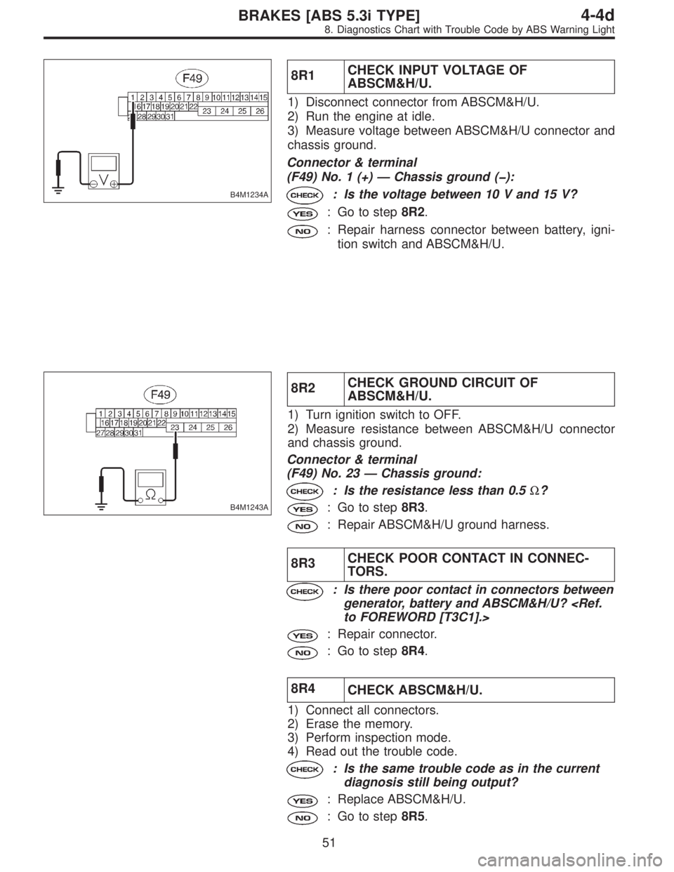
B4M1234A
8R1CHECK INPUT VOLTAGE OF
ABSCM&H/U.
1) Disconnect connector from ABSCM&H/U.
2) Run the engine at idle.
3) Measure voltage between ABSCM&H/U connector and
chassis ground.
Connector & terminal
(F49) No. 1 (+)—Chassis ground (�):
: Is the voltage between 10 V and 15 V?
: Go to step8R2.
: Repair harness connector between battery, igni-
tion switch and ABSCM&H/U.
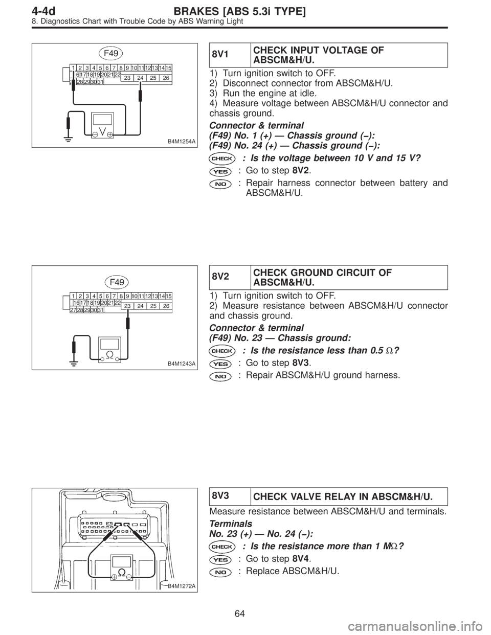
B4M1243A
8R2CHECK GROUND CIRCUIT OF
ABSCM&H/U.
1) Turn ignition switch to OFF.
2) Measure resistance between ABSCM&H/U connector
and chassis ground.
Connector & terminal
(F49) No. 23—Chassis ground:
: Is the resistance less than 0.5Ω?
: Go to step8R3.
: Repair ABSCM&H/U ground harness.
8R3CHECK POOR CONTACT IN CONNEC-
TORS.
: Is there poor contact in connectors between
generator, battery and ABSCM&H/U?
to FOREWORD [T3C1].>
: Repair connector.
: Go to step8R4.
8R4
CHECK ABSCM&H/U.
1) Connect all connectors.
2) Erase the memory.
3) Perform inspection mode.
4) Read out the trouble code.
: Is the same trouble code as in the current
diagnosis still being output?
: Replace ABSCM&H/U.
: Go to step8R5.
51
4-4dBRAKES [ABS 5.3i TYPE]
8. Diagnostics Chart with Trouble Code by ABS Warning Light
Page 2933 of 3342
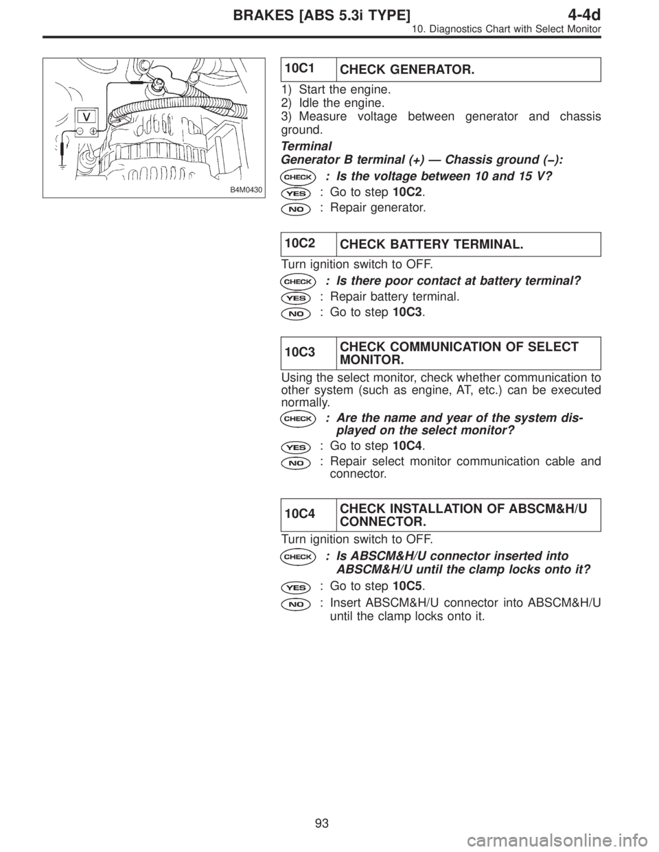
B4M0430
8T1
CHECK GENERATOR.
1) Start engine.
2) Idling after warm-up.
3) Measure voltage between generator B terminal and
chassis ground.
Terminal
Generator B terminal—Chassis ground:
: Is the voltage between 10 V and 17 V?
: Go to step8T2.
: Repair generator.
8T2
CHECK BATTERY TERMINAL.
Turn ignition switch to OFF.
: Are the positive and negative battery termi-
nals tightly clamped?
: Go to step8T3.
: Tighten the clamp of terminal.
B4M1234A
8T3CHECK INPUT VOLTAGE OF
ABSCM&H/U.
1) Disconnect connector from ABSCM&H/U.
2) Run the engine at idle.
3) Measure voltage between ABSCM&H/U connector and
chassis ground.
Connector & terminal
(F49) No. 1 (+)—Chassis ground (�):
: Is the voltage between 10 V and 17 V?
: Go to step8T4.
: Repair harness connector between battery, igni-
tion switch and ABSCM&H/U.
57
4-4dBRAKES [ABS 5.3i TYPE]
8. Diagnostics Chart with Trouble Code by ABS Warning Light
Page 2940 of 3342

B4M1254A
8V1CHECK INPUT VOLTAGE OF
ABSCM&H/U.
1) Turn ignition switch to OFF.
2) Disconnect connector from ABSCM&H/U.
3) Run the engine at idle.
4) Measure voltage between ABSCM&H/U connector and
chassis ground.
Connector & terminal
(F49) No. 1 (+)—Chassis ground (�):
(F49) No. 24 (+)—Chassis ground (�):
: Is the voltage between 10 V and 15 V?
: Go to step8V2.
: Repair harness connector between battery and
ABSCM&H/U.
B4M1243A
8V2CHECK GROUND CIRCUIT OF
ABSCM&H/U.
1) Turn ignition switch to OFF.
2) Measure resistance between ABSCM&H/U connector
and chassis ground.
Connector & terminal
(F49) No. 23—Chassis ground:
: Is the resistance less than 0.5Ω?
: Go to step8V3.
: Repair ABSCM&H/U ground harness.
B4M1272A
8V3
CHECK VALVE RELAY IN ABSCM&H/U.
Measure resistance between ABSCM&H/U and terminals.
Terminals
No. 23 (+)—No. 24 (�):
: Is the resistance more than 1 MΩ?
: Go to step8V4.
: Replace ABSCM&H/U.
64
4-4dBRAKES [ABS 5.3i TYPE]
8. Diagnostics Chart with Trouble Code by ABS Warning Light
Page 2944 of 3342
B4M1234A
8W3CHECK INPUT VOLTAGE OF
ABSCM&H/U.
1) Run the engine at idle.
2) Measure voltage between ABSCM&H/U connector and
chassis ground.
Connector & terminal
(F49) No. 1 (+)—Chassis ground (�):
: Is the voltage between 10 V and 15 V?
: Go to step8W4.
: Repair harness connector between battery, igni-
tion switch and ABSCM&H/U.
B4M1243A
8W4CHECK GROUND CIRCUIT OF
ABSCM&H/U.
1) Turn ignition switch to OFF.
2) Measure resistance between ABSCM&H/U connector
and chassis ground.
Connector & terminal
(F49) No. 23—Chassis ground:
: Is the resistance less than 0.5Ω?
: Go to step8W5.
: Repair ABSCM&H/U ground harness.
8W5
CHECK MOTOR OPERATION.
Operate the sequence control.
NOTE:
Use the diagnosis connector to operate the sequence con-
trol.
: Can motor revolution noise (buzz) be heard
when carrying out the sequence control?
: Go to step8W6.
: Replace ABSCM&H/U.
68
4-4dBRAKES [ABS 5.3i TYPE]
8. Diagnostics Chart with Trouble Code by ABS Warning Light
Page 2969 of 3342

B4M0430
10C1
CHECK GENERATOR.
1) Start the engine.
2) Idle the engine.
3) Measure voltage between generator and chassis
ground.
Terminal
Generator B terminal (+)—Chassis ground (�):
: Is the voltage between 10 and 15 V?
: Go to step10C2.
: Repair generator.
10C2
CHECK BATTERY TERMINAL.
Turn ignition switch to OFF.
: Is there poor contact at battery terminal?
: Repair battery terminal.
: Go to step10C3.
10C3CHECK COMMUNICATION OF SELECT
MONITOR.
Using the select monitor, check whether communication to
other system (such as engine, AT, etc.) can be executed
normally.
: Are the name and year of the system dis-
played on the select monitor?
: Go to step10C4.
: Repair select monitor communication cable and
connector.
10C4CHECK INSTALLATION OF ABSCM&H/U
CONNECTOR.
Turn ignition switch to OFF.
: Is ABSCM&H/U connector inserted into
ABSCM&H/U until the clamp locks onto it?
: Go to step10C5.
: Insert ABSCM&H/U connector into ABSCM&H/U
until the clamp locks onto it.
93
4-4dBRAKES [ABS 5.3i TYPE]
10. Diagnostics Chart with Select Monitor
Page 2970 of 3342
B4M1234A
10C5CHECK POWER SUPPLY OF
ABSCM&H/U.
1) Disconnect connector from ABSCM&H/U.
2) Start engine.
3) Idle the engine.
4) Measure voltage between ABSCM&H/U connector and
chassis ground.
Connector & terminal
(F49) No. 1 (+)—Chassis ground (�):
: Is the voltage between 10 and 15 V?
: Go to step10C6.
: Repair ABSCM&H/U power supply circuit.
B4M1243A
10C6CHECK GROUND CIRCUIT OF
ABSCM&H/U.
1) Turn ignition switch to OFF.
2) Measure resistance between ABSCM&H/U connector
and chassis ground.
Connector & terminal
(F49) No. 23—Chassis ground:
: Is the resistance less than 0.5Ω?
: Repair harness/connector between ABSCM&H/U
and select monitor.
: Go to step10C7.
94
4-4dBRAKES [ABS 5.3i TYPE]
10. Diagnostics Chart with Select Monitor
Page 3002 of 3342
B4M1234A
10Q1CHECK INPUT VOLTAGE OF
ABSCM&H/U.
1) Turn ignition switch to OFF.
2) Disconnect connector from ABSCM&H/U.
3) Run the engine at idle.
4) Measure voltage between ABSCM&H/U connector and
chassis ground.
Connector & terminal
(F49) No. 1 (+)—Chassis ground (�):
: Is the voltage between 10 V and 15 V?
: Go to step10Q2.
: Repair harness connector between battery, igni-
tion switch and ABSCM&H/U.
B4M1243A
10Q2CHECK GROUND CIRCUIT OF
ABSCM&H/U.
1) Turn ignition switch to OFF.
2) Measure resistance between ABSCM&H/U connector
and chassis ground.
Connector & terminal
(F49) No. 23—Chassis ground:
: Is the resistance less than 0.5Ω?
: Go to step10Q3.
: Repair ABSCM&H/U ground harness.
10Q3CHECK POOR CONTACT IN CONNEC-
TORS.
: Is there poor contact in connectors between
generator, battery and ABSCM&H/U?
to FOREWORD [T3C1].>
: Repair connector.
: Go to step10Q4.
126
4-4dBRAKES [ABS 5.3i TYPE]
10. Diagnostics Chart with Select Monitor
Page 3006 of 3342
B4M1234A
10U1CHECK INPUT VOLTAGE OF
ABSCM&H/U.
1) Turn ignition switch to OFF.
2) Disconnect connector from ABSCM&H/U.
3) Run the engine at idle.
4) Measure voltage between ABSCM&H/U connector and
chassis ground.
Connector & terminal
(F49) No. 1 (+)—Chassis ground (�):
: Is the voltage between 10 V and 15 V?
: Go to step10U2.
: Repair harness connector between battery, igni-
tion switch and ABSCM&H/U.
B4M1243A
10U2CHECK GROUND CIRCUIT OF
ABSCM&H/U.
1) Turn ignition switch to OFF.
2) Measure resistance between ABSCM&H/U connector
and chassis ground.
Connector & terminal
(F49) No. 23—Chassis ground:
: Is the resistance less than 0.5Ω?
: Go to step10U3.
: Repair ABSCM&H/U ground harness.
10U3CHECK POOR CONTACT IN CONNEC-
TORS.
: Is there poor contact in connectors between
generator, battery and ABSCM&H/U?
to FOREWORD [T3C1].>
: Repair connector.
: Go to step10U4.
130
4-4dBRAKES [ABS 5.3i TYPE]
10. Diagnostics Chart with Select Monitor