Page 921 of 2053

SECTION 4A
HYDRAULIC BRAKES
CAUTION: Disconnect the negative battery cable before removing or installing any electrical unit or when
a tool or equipment could easily come in contact with exposed electrical terminals. Disconnecting this
cable will help prevent personal injury and damage to the vehicle. The ignition must also be in LOCK
unless otherwise noted.
TABLE OF CONTENTS
Description and Operation...................................4A-2
General Description.............................................4A-2
Diagnostic Information and Procedures..............4A-3
Brake System Testing ..........................................4A-3
Brake Hose Inspection.........................................4A-3
Brake Warning Lamp Circuit Description..............4A-4
Brake Warning Lamp Diagnosis...........................4A-5
LCRV (Load Conscious Reducing Valve)..............4A-8
Repair Instructions..............................................4A-10On-Vehicle Service...............................................4A-10
Manual Bleeding The Brakes.............................4A-10
Front Brake Hose...............................................4A-13
Rear Brake Hose...............................................4A-13
Stoplamp Switch................................................4A-14
Brake Pedal.......................................................4A-14
Specifications.....................................................4A-15
General Specification .........................................4A-15
Fastener Tightening Specifications.....................4A-16
Page 930 of 2053

SSAMGYONG MY2002
4A-10 HYDRAULIC BRAKES
KAA4A020
KAA4A030
Notice: Keep brake fluid away from painted surfaces
because brake fluid will damage the paint finish.
2. Fill the master cylinder reservoir with brake fluid.
Keep the master cylinder reservoir at least one-
half full during the bleeding operation.
ON-VEHICLE SERVICE
MANUAL BLEEDING THE BRAKES
Removal and Installation Procedure
Important: Manual bleeding of the hydraulic modulator
is not possible. If air enters the antilock brake hydraulic
modulator, or if an unfilled modulator is installed, use
the scan tool to bleed air out of the brake system.
Replacement modulators are shipped already filled
and bled. In normal on-vehicle service procedures
involving the modulator, such as the procedure to
replace the electronic brake control module, air will
not enter the modulator. In such cases, use the
bleeding procedure in this section.
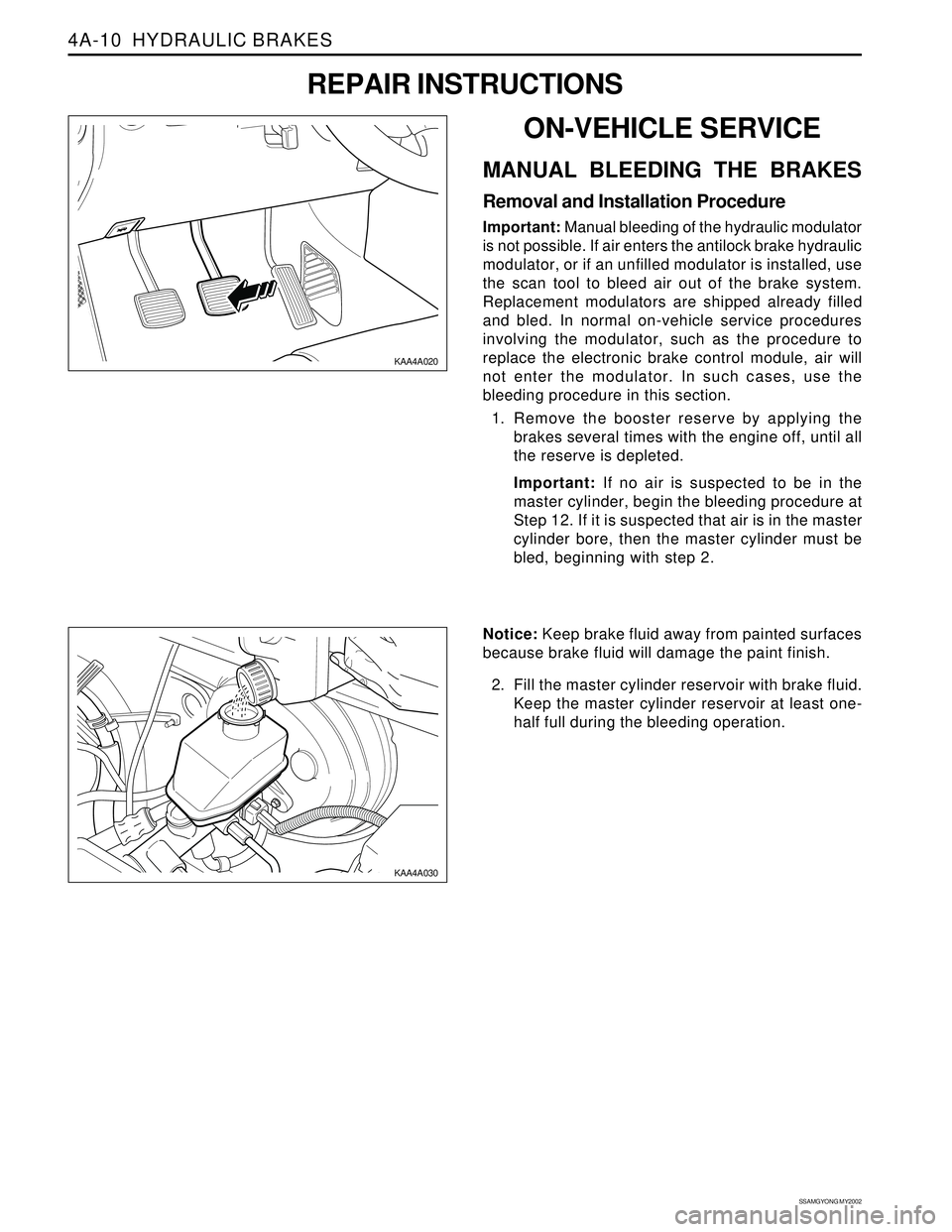
1. Remove the booster reserve by applying the
brakes several times with the engine off, until all
the reserve is depleted.
Important: If no air is suspected to be in the
master cylinder, begin the bleeding procedure at
Step 12. If it is suspected that air is in the master
cylinder bore, then the master cylinder must be
bled, beginning with step 2.
REPAIR INSTRUCTIONS
Page 937 of 2053
Description and Operation...................................4B-2
General Description.............................................4B-2
Component Locator.............................................4B-3
Repair Instructions................................................4B-4
On-Vehicle Service.................................................4B-4Brake Oil Level Switch .........................................4B-4
Brake Fluid Reservoir ...........................................4B-4
Master Cylinder...................................................4B-5
Specifications.......................................................4B-8
Fastener Tightening Specifications.......................4B-8
SECTION 4B
MASTER CYLINDER
TABLE OF CONTENTS
Page 938 of 2053

SSANGYONG MY2002
4B-2 MASTER CYLINDER
DESCRIPTION AND OPERATION
GENERAL DESCRIPTION
The master cylinder is designed for use in a parallel
split system. One front and one parallel to rear brakes
are served by the primary piston. The opposite front
and rear brakes are served by the secondary piston.
The master cylinder incorporates the functions of the
standard dual master cylinder, plus a low fluid level
indicator. The brake fluid level switch is attached under
the body of the plastic brake master cylinder reservoir.
Notice: Do not use lubricated shop air on the brake
parts, because oil will damage the rubber components.Important:•Replace all the components included in the repair
kits used to service the master cylinder.
Lubricate the rubber parts with clean brake fluid to
ease assembly.
If any hydraulic component is removed or discon-
nected, it may be necessary to bleed all or part of
the brake system. Refer to Section 4F, Antilock
Brake System and Traction Control System.
The torque values specified are for dry, unlubricated
fasteners.
Perform all service operations on a clean bench,
free from all traces of mineral oil.
Page 940 of 2053
SSANGYONG MY2002
4B-4 MASTER CYLINDER
ON-VEHICLE SERVICE
BRAKE OIL LEVEL SWITCH
Removal and Installation Procedure
1. Disconnect the brake fluid level switch connector.
2. Disconnect the switch wiring connector.
3. Disconnect the switch from the brake oil tank.
4. Installation should follow the removal procedure
in the reverse order.
REPAIR INSTRUCTIONS
BRAKE FLUID RESERVOIR
Removal and Installation Procedure
Important: Remove the brake fluid reservoir only when
it must be replaced because of damage or leaks.
1. Disconnect the brake fluid level switch connector.
2. Drain the brake fluid.
KAA4B020
KAA4B020
KAA4B050
3. Remove the brake fluid reservoir fromthe master
cylinder body by tilting the reservoir and pulling
it up-ward.
Page 944 of 2053
Description and Operation....................................4C-2
General Description..............................................4C-2
Component Locator..............................................4C-3
Diagnostic Information and Procedures...............4C-4
Power Booster Functional Check..........................4C-4
Repair Instructions................................................4C-5On-Vehicle Service.................................................4C-5
Power Booster Assembly.....................................4C-5
Vacuum Hose......................................................4C-6
Specifications.......................................................4C-7
General Specification ...........................................4C-7
Fastener Tightening Specifications.......................4C-7
SECTION 4C
POWER BOOSTER
TABLE OF CONTENTS
Page 945 of 2053
SSANGYONG MY2002
4C-2 POWER BOOSTER
DESCRIPTION AND OPERATION
GENERAL DESCRIPTION
The power booster is a double-diaphragm, vacuum-sus
pended unit. In normal operating mode, with the service
brakes in the release position, a vacuum-suspended
booster operates with a vacuum on both sides of its
diaphragm. When the brakes are applied, air at
atmospheric pressure is admitted to one side of the
diaphragm to provide the power assist.When the brakes are released, atmospheric air is shut
off from that side of the diaphragm. The air is then
drawn from the booster through the vacuum check
valve by the vacuum source.
Important: If any hydraulic component is removed or
disconnected, it may be necessary to bleed all or part
of the brake system. Refer to Section 4F, Antilock
Brake System and Traction Control System.
Page 948 of 2053
POWER BOOSTER 4C-5
SSANGYONG MY2002
REPAIR INSTRUCTIONS
KAA4C030
KAA4A040
KAA4C050
ON-VEHICLE SERVICE
POWER BOOSTER ASSEMBLY
Removal and Installation Procedure
1. Remove the master cylinder. Refer to Section 4B,
Master Cylinder.
2. Remove the vacuum hose from the booster.
3. Remove the clevis pin and disconnect the pedal
and brake booster push rod.
Installation Notice:
•Apply the grease around the hole of clevis pin.
4. Remove the power booster mounting nuts and re-
move the booster from the dash panel.
Installation Notice
Tightening Torque 17 Nm (13 lb-ft)
Install the new gasket.
5. Installation should follow the removal procedure
in the reverse order.