1997 SSANGYONG KORANDO service
[x] Cancel search: servicePage 1360 of 2053
CLUTCH 5C-5
SSANGYONG MY2002
ON-VEHICLE SERVICE
BLEEDING OF CLUTCH SYSTEM
Bleeding procedure
Notice: Keep the fluid level over ‘MAX’ in reservoir
during bleeding operation.
Do not let fluid contact a painted surface.
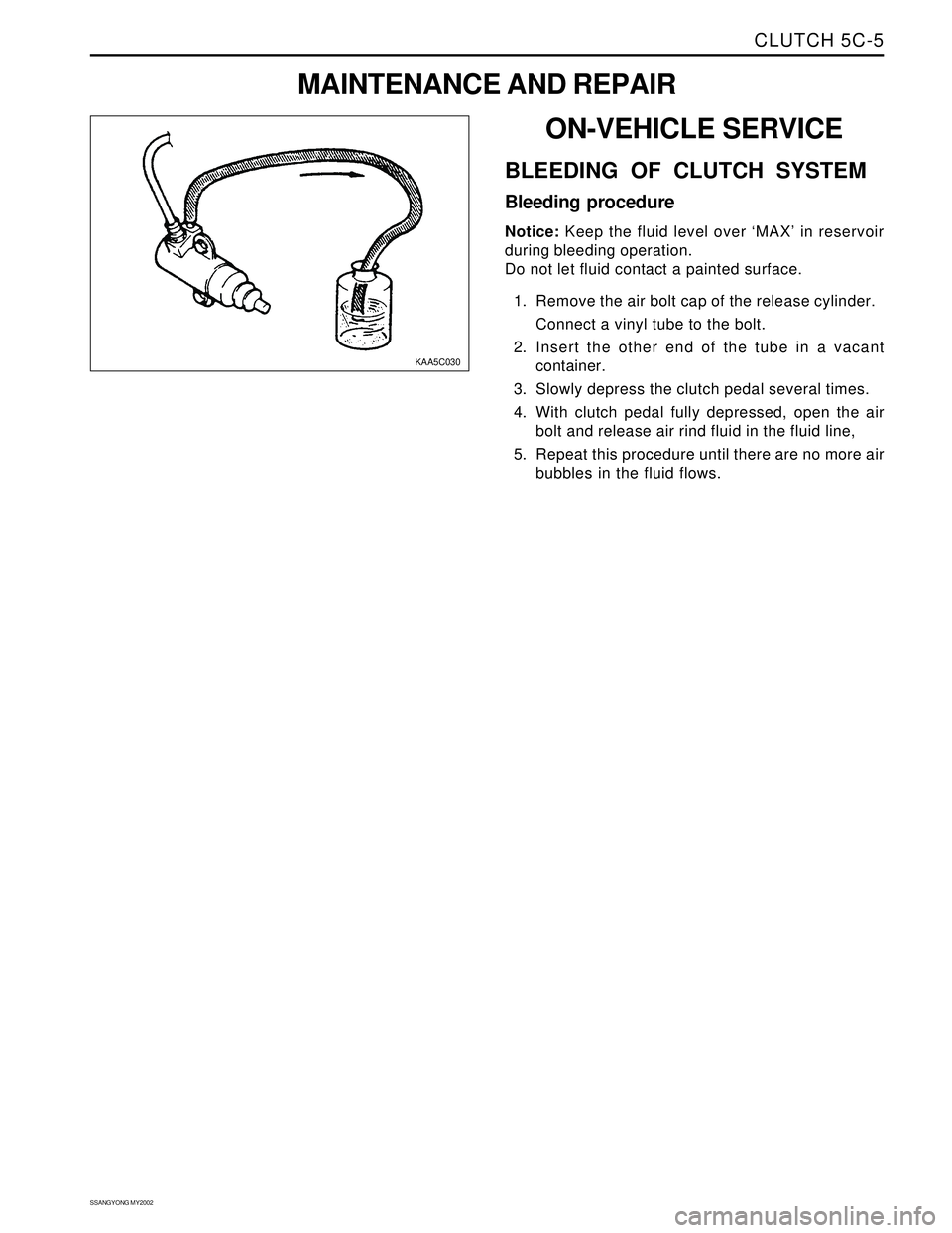
1. Remove the air bolt cap of the release cylinder.
Connect a vinyl tube to the bolt.
2. Insert the other end of the tube in a vacant
container.
3. Slowly depress the clutch pedal several times.
4. With clutch pedal fully depressed, open the air
bolt and release air rind fluid in the fluid line,
5. Repeat this procedure until there are no more air
bubbles in the fluid flows.
KAA5C030
MAINTENANCE AND REPAIR
Page 1372 of 2053
SECTION 5D1
TRANSFER CASE (TOD)
CAUTION: Disconnect the negative battery cable before removing or installing any electrical unit or when a
tool or equipment could easily come in contact with exposed electrical terminals. Disconnecting this cable
will help prevent personal injury and damage to the vehicle. The ignition must also be in LOCK unless
other-wise noted.
TABLE OF CONTENTS
Description and Operation.................................5D1-2
Torque on Demand (TOD) System
Transfer Case.................................................5D1-2
Transfer Case Control Unit (TCCU).....................5D1-2
TCCU Coding....................................................5D1-2
Pin Description..................................................5D1-3
Components of the TOD Transfer Case System ..5D1-4
Definition of Terminology....................................5D1-4
Operation of the TOD Transfer Case System......5D1-4
Component Locator...........................................5D1-7
Torque on Demand (TOD) Type Transfer Case....5D1-7
Transfer Case Disassembled View.....................5D1-8
TOD Control Unit..............................................5D1-10
Diagnosis..........................................................5D1-11
Self-Diagnostic Tests.......................................5D1-11
Diagnostic Trouble Codes (DTCs)....................5D1-12
Clearing Diagnostic Trouble Codes..................5D1-12
4WD Check Indicator Stays on with Ignition
Switch ON....................................................5D1-14
4WD Low Indicator Stays on with Ignition
Switch ON....................................................5D1-16
No 4WD Check or 4WD Low Indicator with
Ignition Switch ON........................................5D1-18
4WD Low Indicator Blink Steadily.....................5D1-20
TCCU Diagnostic System Check......................5D1-21
DTC 1714 Eeprom Checksum Fault..................5D1-22
DTC 1715 Tp Sensor Loss of Signal.................5D1-24
DTC 1716 Tp Sensor Out of Range...................5D1-26
DTC 1721 Electromagnetic Clutch Open / Short
to Battery.....................................................5D1-28
DTC 1722 Electromagnetic Clutch Short to
Ground.........................................................5D1-32
DTC 1731 Front Speed Sensor Voltage Low......5D1-36
DTC 1732 Front Speed Sensor Voltage High.....5D1-38DTC 1733 Rear Speed Sensor Voltage Low......5D1-40
DTC 1734 Rear Speed Sensor Voltage High.....5D1-42
DTC 1735 Speed Sensor Reference Voltage
Low ..............................................................5D1-44
DTC 1736 Speed Sensor Reference Voltage
High.............................................................5D1-46
DTC 1741 Motor Output Open / Shorted
to Battery.....................................................5D1-48
DTC 1742 Motor Output Shorted to Ground......5D1-52
DTC 1743 Shift System Timeout.......................5D1-55
DTC 1750 General Position Encoder Fault
(Invalid Code)...............................................5D1-56
DTC 1751 Position 1 Shorted to Ground............5D1-58
DTC 1752 Position 2 Shorted to Ground............5D1-60
DTC 1753 Position 3 Shorted to Ground............5D1-62
DTC 1754 Position 4 Shorted to Ground............5D1-64
Repair Instructions............................................5D1-66
On-Vehicle Service.............................................5D1-66
Oil Replacement..............................................5D1-66
Transfer Case Control Unit (TCCU)...................5D1-67
Transfer Case..................................................5D1-67
Shift Motor.......................................................5D1-69
Front and Rear Propeller Shaft Speed Sensor ...5D1-70
Unit Repair........................................................5D1-71
Transfer Case Overhaul...................................5D1-71
Specifications...................................................5D1-79
General Specification.......................................5D1-79
TCCU Electric Characteristics..........................5D1-79
Fastener Tightening Specifications...................5D1-79
Schematic and Routing Diagram....................5D1-80
TOD Transfer Case Control Unit (TCCU)............5D1-80
Special Tools and Equipment..........................5D1-82
Special Tool Table ...........................................5D1-82
Page 1382 of 2053
SSANGYONG MY2002
5D1-12 TRANSFER CASE
Both Speed Sensor Faulty
If both the front and rear speed sensors are faulty con
tinuously for 0.5 seconds the 4WD CHECK lamp is
illuminated. The TCCU then responds as follows:
1. If the system is in high range the TCCU sets the
EMC touch off level based on a vehicle speed of
0 and wheel slip control is suspended.
2. If the system is in low range, the EMC duty cycle
is set to maximum until the system is shifted out
of low range.
3. All electric shift activity is halted until the Ignition
is cycled. If a shift is in progress it will be
completed.
If both speed sensors recover continuously for 0.5 sec-
ond the TCCU will function normally. The 4WD CHECK
lamp is turned off but the fault code will remain in
memory.
Electro-Magnetic Clutch Test
The electromagnetic clutch (EMC) is tested for open
circuit or short circuit to ground. If a fault is detected
continuously for 0.8 second the 4WD CHECK lamp is
turned on and all TODTM activity is halted.
If the EMC recovers continuously for 0.8 second the
TCCU will function normally. The 4WD CHECK lamp is
turned off but the fault code will remain in memory.
DIAGNOSTIC TROUBLE CODES
(DTCS)
When a fault is detected a diagnostic trouble code
(DTC) is stored in the TCCU and illuminates the 4WD
CHECK indicator. This DTC will remain in memory until
the TCCU is instructed to erase DTCs by scan tool.
Notice: DTCs can not be erased by disconnecting of
power supply to the TCCU.
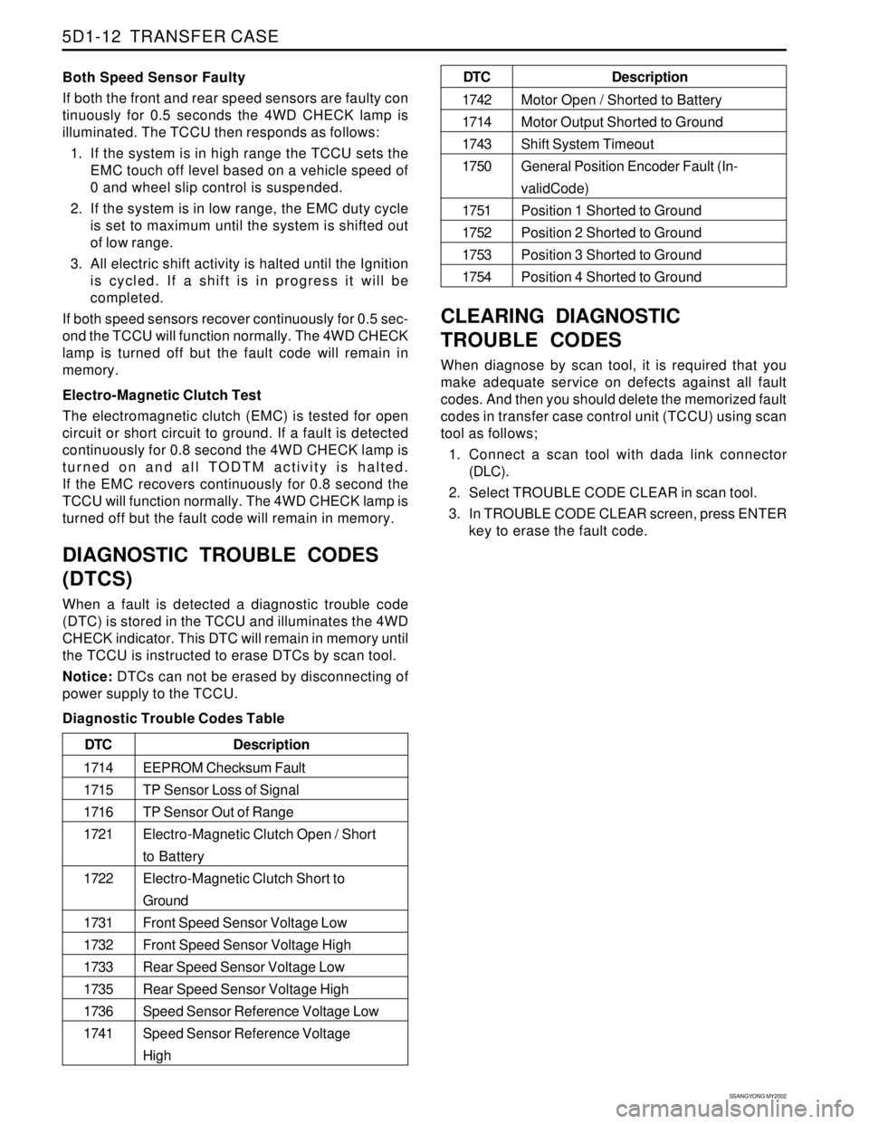
Diagnostic Trouble Codes Table
CLEARING DIAGNOSTIC
TROUBLE CODES
When diagnose by scan tool, it is required that you
make adequate service on defects against all fault
codes. And then you should delete the memorized fault
codes in transfer case control unit (TCCU) using scan
tool as follows;
1. Connect a scan tool with dada link connector
(DLC).
2. Select TROUBLE CODE CLEAR in scan tool.
3. In TROUBLE CODE CLEAR screen, press ENTER
key to erase the fault code.
Description
EEPROM Checksum Fault
TP Sensor Loss of Signal
TP Sensor Out of Range
Electro-Magnetic Clutch Open / Short
to Battery
Electro-Magnetic Clutch Short to
Ground
Front Speed Sensor Voltage Low
Front Speed Sensor Voltage High
Rear Speed Sensor Voltage Low
Rear Speed Sensor Voltage High
Speed Sensor Reference Voltage Low
Speed Sensor Reference Voltage
High DTC
1714
1715
1716
1721
1722
1731
1732
1733
1735
1736
1741
Description
Motor Open / Shorted to Battery
Motor Output Shorted to Ground
Shift System Timeout
General Position Encoder Fault (In-
validCode)
Position 1 Shorted to Ground
Position 2 Shorted to Ground
Position 3 Shorted to Ground
Position 4 Shorted to Ground DTC
1742
1714
1743
1750
1751
1752
1753
1754
Page 1388 of 2053
SSANGYONG MY2002
5D1-66 TRANSFER CASE
KAA5D240
KAA5D250
ON-VEHICLE SERVICE
OIL REPLACEMENT
Important: Use only recommended oil or not the trans-
fer case will be severely damaged. Inspect every
10,000 km and replace every 60,000 km.
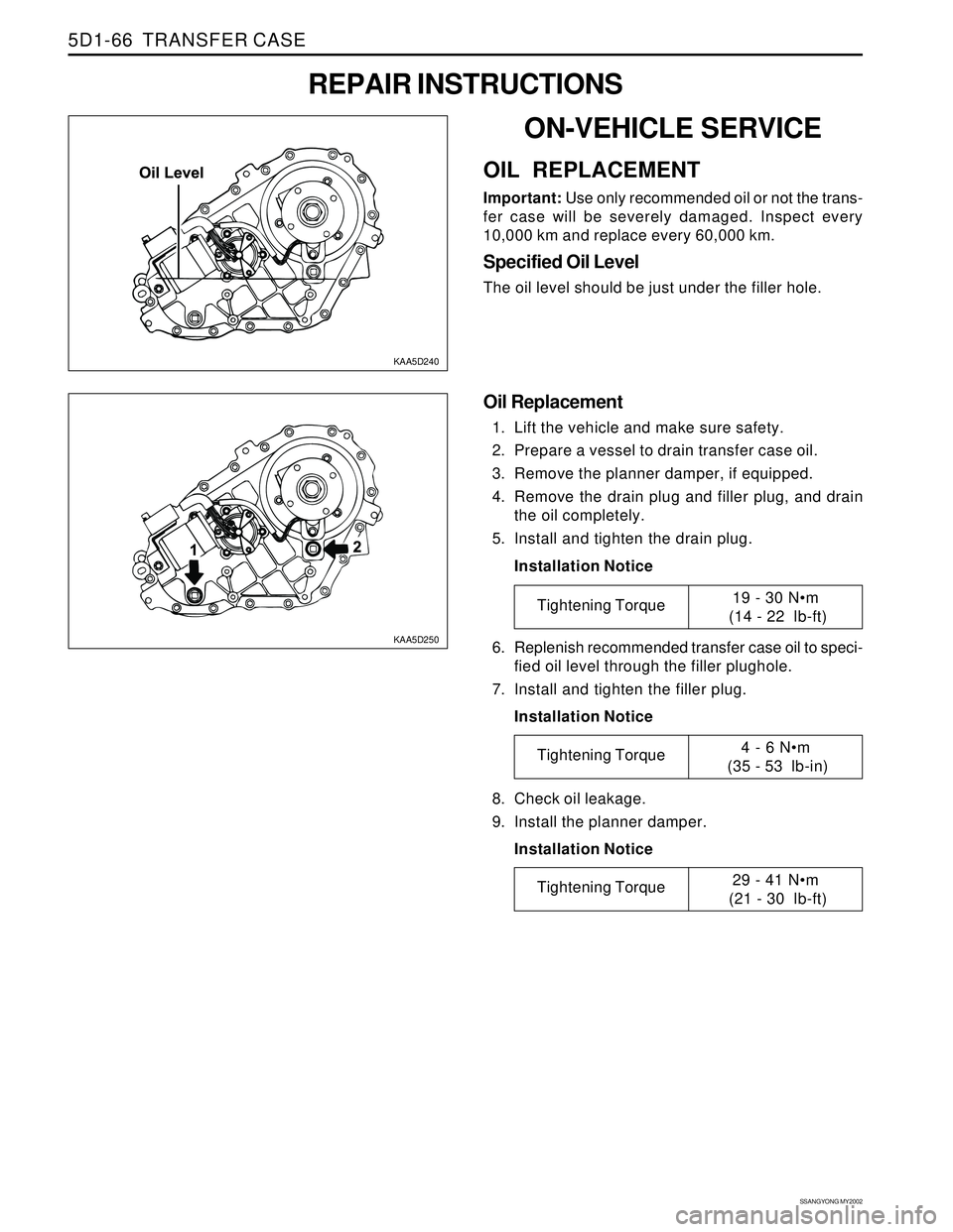
Specified Oil Level
The oil level should be just under the filler hole.
REPAIR INSTRUCTIONS
Oil Replacement
1. Lift the vehicle and make sure safety.
2. Prepare a vessel to drain transfer case oil.
3. Remove the planner damper, if equipped.
4. Remove the drain plug and filler plug, and drain
the oil completely.
5. Install and tighten the drain plug.
Installation Notice
6. Replenish recommended transfer case oil to speci-
fied oil level through the filler plughole.
7. Install and tighten the filler plug.
Installation Notice
8. Check oil leakage.
9. Install the planner damper.
Installation Notice
Tightening Torque19 - 30 Nm
(14 - 22 lb-ft)
Tightening Torque4 - 6 Nm
(35 - 53 lb-in)
Tightening Torque29 - 41 Nm
(21 - 30 lb-ft)
Page 1395 of 2053
TRANSFER CASE 5D1-73
SSANGYONG MY2002
KAA5D430
KAA5D440
KAA5D450
KAA5D460
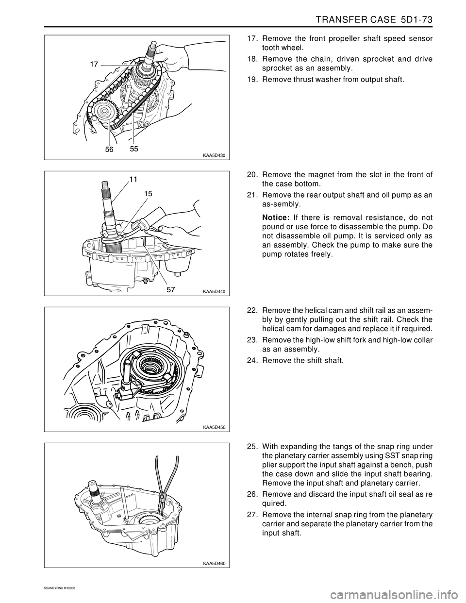
17. Remove the front propeller shaft speed sensor
tooth wheel.
18. Remove the chain, driven sprocket and drive
sprocket as an assembly.
19. Remove thrust washer from output shaft.
25. With expanding the tangs of the snap ring under
the planetary carrier assembly using SST snap ring
plier support the input shaft against a bench, push
the case down and slide the input shaft bearing.
Remove the input shaft and planetary carrier.
26. Remove and discard the input shaft oil seal as re
quired.
27. Remove the internal snap ring from the planetary
carrier and separate the planetary carrier from the
input shaft. 22. Remove the helical cam and shift rail as an assem-
bly by gently pulling out the shift rail. Check the
helical cam for damages and replace it if required.
23. Remove the high-low shift fork and high-low collar
as an assembly.
24. Remove the shift shaft. 20. Remove the magnet from the slot in the front of
the case bottom.
21. Remove the rear output shaft and oil pump as an
as-sembly.
Notice: If there is removal resistance, do not
pound or use force to disassemble the pump. Do
not disassemble oil pump. It is serviced only as
an assembly. Check the pump to make sure the
pump rotates freely.
Page 1401 of 2053
SECTION 5D2
TRANSFER CASE (PART TIME - 4408)
TABLE OF CONTENTS
General Infromation and Operation..................5D2-2
4WD Operation Overview...................................5D2-2
System Structure...............................................5D2-3
2H Mode (Rear Wheel Drive)..............................5D2-5
4H Mode (4WD Drive - High Speed)...................5D2-6
4H Mode (4WD Drive - Low Speed)....................5D2-7
System Description...........................................5D2-8
Specifications....................................................5D2-9
Diagnostic Infromation and Procedures..........5D2-10
General Diagnosis...........................................5D2-10
Self-Diagnosis Test..........................................5D2-11
Diagnostic Diagram .........................................5D2-15
Component Locator .........................................5D2-16
Cross Sectional View.......................................5D2-16Transfer Case Assembly..................................5D2-17
Disassembly and Assembly............................5D2-18
Maintenance and Repair.................................5D2-20
On-Vehicle Service.............................................5D2-20
Maintenance of Transfer Case Lubricant...........5D2-20
4H and 4L Indicator .........................................5D2-21
TCCU Inspection.............................................5D2-21
Transfer Case Assembly..................................5D2-22
TCCU..............................................................5D2-24
Unit Repair........................................................5D2-25
Disassembly Procedure...................................5D2-25
Assembly Procedure.......................................5D2-35
Page 1411 of 2053
TRANSFER CASE (PART TIME - 4408) 5D2-11
SSANGYONG MY2002
KAA5D080
KAA5D090
KAA5D100
SELF-DIAGNOSIS TEST
System Description
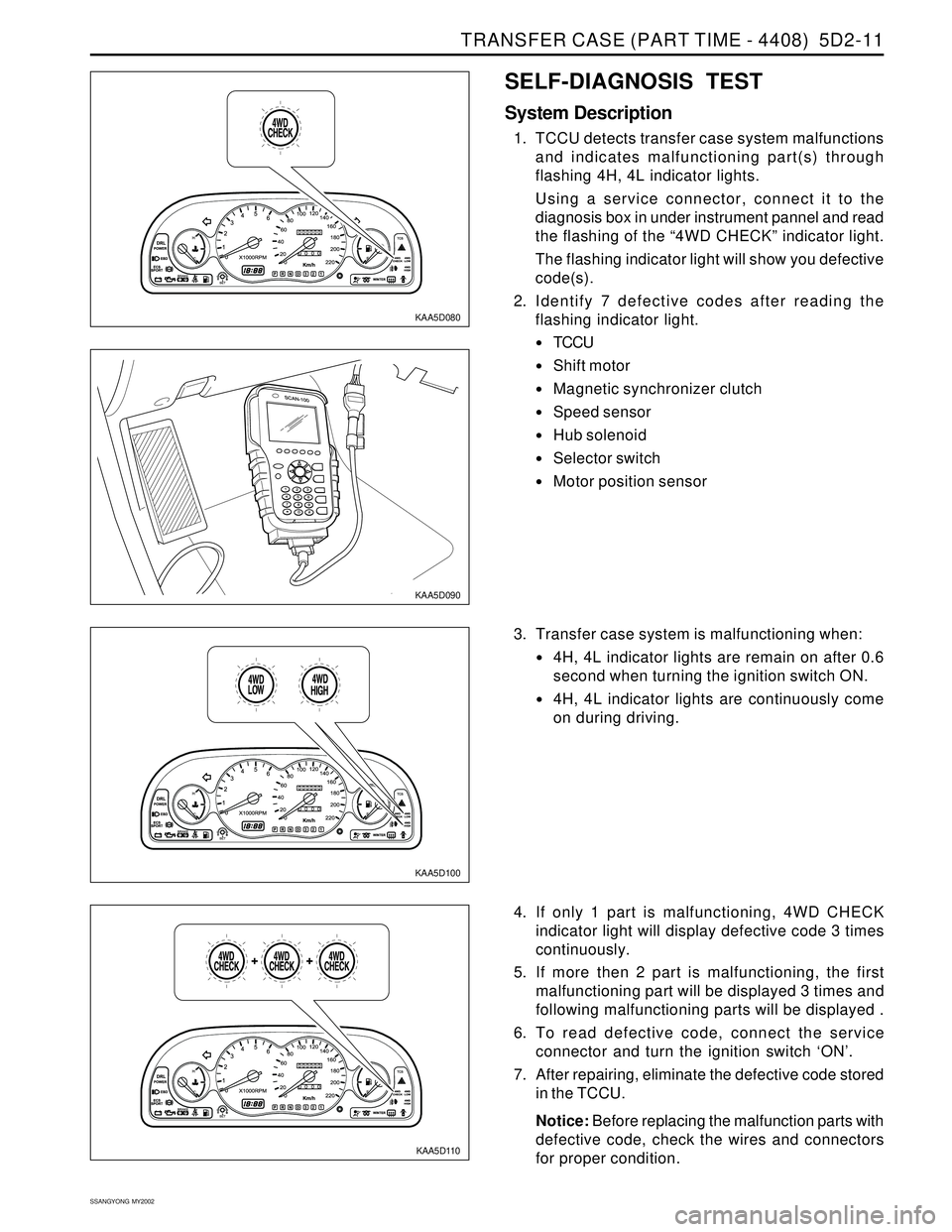
1. TCCU detects transfer case system malfunctions
and indicates malfunctioning part(s) through
flashing 4H, 4L indicator lights.
Using a service connector, connect it to the
diagnosis box in under instrument pannel and read
the flashing of the “4WD CHECK” indicator light.
The flashing indicator light will show you defective
code(s).
2. Identify 7 defective codes after reading the
flashing indicator light.
TCCU
Shift motor
Magnetic synchronizer clutch
Speed sensor
Hub solenoid
Selector switch
Motor position sensor
KAA5D110
3. Transfer case system is malfunctioning when:
4H, 4L indicator lights are remain on after 0.6
second when turning the ignition switch ON.
4H, 4L indicator lights are continuously come
on during driving.
4. If only 1 part is malfunctioning, 4WD CHECK
indicator light will display defective code 3 times
continuously.
5. If more then 2 part is malfunctioning, the first
malfunctioning part will be displayed 3 times and
following malfunctioning parts will be displayed .
6. To read defective code, connect the service
connector and turn the ignition switch ‘ON’.
7. After repairing, eliminate the defective code stored
in the TCCU.
Notice: Before replacing the malfunction parts with
defective code, check the wires and connectors
for proper condition.
Page 1412 of 2053
SSANGYONG MY2002
5D2-12 TRANSFER CASE (PART TIME - 4408)
KAA5D120
KAA5D130
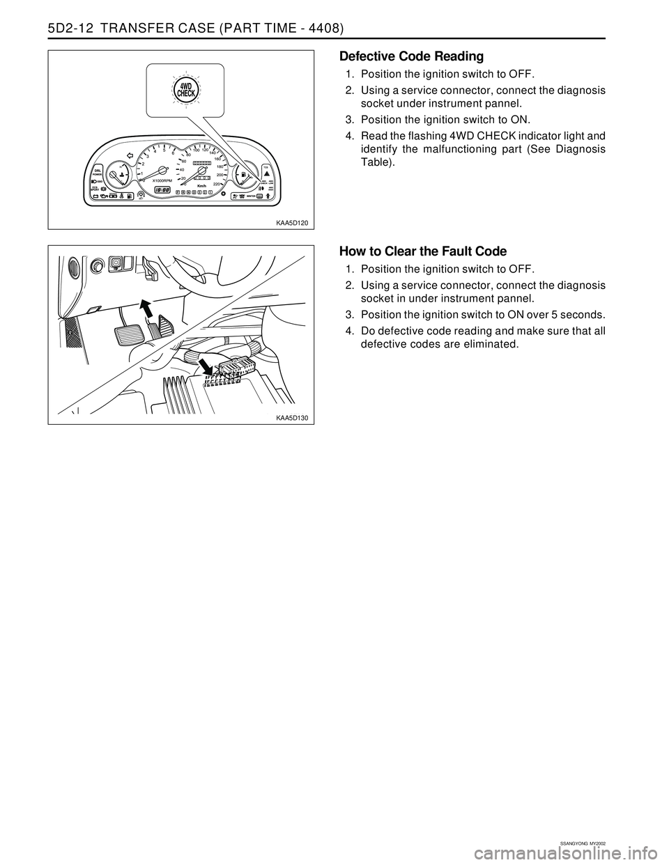
Defective Code Reading
1. Position the ignition switch to OFF.
2. Using a service connector, connect the diagnosis
socket under instrument pannel.
3. Position the ignition switch to ON.
4. Read the flashing 4WD CHECK indicator light and
identify the malfunctioning part (See Diagnosis
Table).
How to Clear the Fault Code
1. Position the ignition switch to OFF.
2. Using a service connector, connect the diagnosis
socket in under instrument pannel.
3. Position the ignition switch to ON over 5 seconds.
4. Do defective code reading and make sure that all
defective codes are eliminated.