Page 1465 of 2053
SSANGYONG MY2002
6B-4 POWER STEERING PUMP
KAA6B010
REPAIR INSTRUCTIONS
ON-VEHICLE SERVICE
SERPENTINE ACCESSORY DRIVE
BELT
Removal and Installation Procedure
1. Remove the electric cooling fan. Refer to Section
1D, Engine Cooling.
2. Use a wrench to turn the tensioner bolt clockwise,
compressing the tensioner, and releasing the
tension on the serpentine accessory drive bolt.
KAA6B020
3. Remove the serpentine accessory drive belt.
Page 1467 of 2053
SSANGYONG MY2002
6B-6 POWER STEERING PUMP
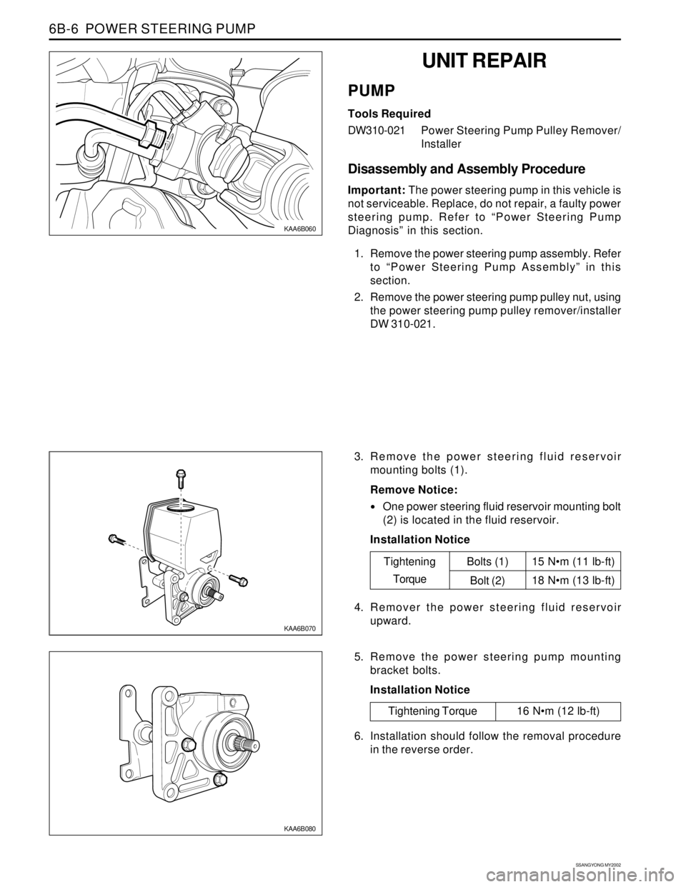
KAA6B060
KAA6B070
3. Remove the power steering fluid reservoir
mounting bolts (1).
Remove Notice:
One power steering fluid reservoir mounting bolt
(2) is located in the fluid reservoir.
Installation Notice
KAA6B080
5. Remove the power steering pump mounting
bracket bolts.
Installation Notice
UNIT REPAIR
PUMP
Tools Required
DW310-021Power Steering Pump Pulley Remover/
Installer
Disassembly and Assembly Procedure
Important: The power steering pump in this vehicle is
not serviceable. Replace, do not repair, a faulty power
steering pump. Refer to “Power Steering Pump
Diagnosis” in this section.
1. Remove the power steering pump assembly. Refer
to “Power Steering Pump Assembly” in this
section.
2. Remove the power steering pump pulley nut, using
the power steering pump pulley remover/installer
DW 310-021.
Tightening Torque 16 Nm (12 lb-ft)15 Nm (11 lb-ft)
18 Nm (13 lb-ft)
Tightening
TorqueBolts (1)
Bolt (2)
4. Remover the power steering fluid reservoir
upward.
6. Installation should follow the removal procedure
in the reverse order.
Page 1469 of 2053
SECTION 6C
POWER STEERING GEAR
TABLE OF CONTENTS
Description and Operation...................................6C-2
Power Rack and Pinion........................................6C-2
Component Locator.............................................6C-3
Diagnostic Information and Procedures..............6C-4
Power Steering Rack and Pinion Gear...................6C-4
Power Steering Rack and Pinion Gear Bench
Testing.............................................................6C-6
Straight-Ahead Check ..........................................6C-6
Repair Instructions................................................6C-8
On-Vehicle Service.................................................6C-8
Rack and Pinion Assembly..................................6C-8
Outer Tie Rod......................................................6C-9Dust Boot.......................................................... 6C-10
Intermediate Shaft............................................. 6C-10
Hydraulic Cylinder Lines.................................... 6C-11
Unit Repair.......................................................... 6C-13
Rack and Pinion................................................ 6C-13
Valve and Pinion Assembly................................ 6C-14
Rack Bearing.................................................... 6C-15
Rack Bearing Preload Adjustment...................... 6C-16
Specifications..................................................... 6C-17
Fastener Tightening Specifications..................... 6C-17
Special Tools and Equipment............................ 6C-18
Special Tools Table............................................ 6C-18
Page 1476 of 2053
SSANGYONG MY2002
6C-8 POWER STEERING GEAR
KAA6C040
KAA6C030
ON-VEHICLE SERVICE
RACK AND PINION ASSEMBLY
Tools Required
661 589 13 33 00 Ball Joint Remover
Removal and Installation Procedure
1. Raise and suitably support the vehicle.
2. Remove the wheels. Refer to Section 2E, Tires
and Wheels.
3. Remove the intermediate shaft. Refer to
“Intermediate shaft” in this section.
4. Disconnect the return line pipe from the power
steering gear outlet. Place a drain pan under the
steering gear to catch the power steering fluid.
Installation Notice
REPAIR INSTRUCTIONS
Tightening Torque 17 Nm (13 lb-ft)
5. Disconnect the pressure line pipe from the power
steering gear inlet.
Installation Notice
Tightening Torque 17 Nm (13 lb-ft)
Page 1487 of 2053
SECTION 6E
POWER STEERING AND COLUMN
TABLE OF CONTENTS
Description and Operation...................................6E-2
General Description.............................................6E-2
Ignition Switch Keyhole Lamp..............................6E-2
Ignition Key Reminder .........................................6E-2
Component Locator.............................................6E-3
Diagnostic Information and Procedures..............6E-4
Steering Wheel Freeplay Inspection.....................6E-4
Steering Effort Inspection.....................................6E-4
Steering Column Diagnosis..................................6E-5
Repair Instructions................................................6E-9On-Vehicle Service.................................................6E-9
Headlamp/Turn Signal Switch and Lever...............6E-9
Wiper Switch and Lever.....................................6E-10
Steering Wheel With Sir.....................................6E-10
Ignition Lock Cylinder and Switch......................6E-11
Steering Column................................................6E-12
Specifications.....................................................6E-14
Fastener Tightening Specifications.....................6E-14
Special Tools and Equipment............................6E-15
Special Tools Table............................................6E-15
Page 1495 of 2053
POWER STEERING AND COLUMN 6E-9
SSANGYONG MY2002
KAA6E060
KAA6E040
ON-VEHICLE SERVICE
HEADLAMP/TURN SIGNAL
SWITCH AND LEVER
Removal and Installation Procedure
1. Disconnect the negative battery cable.
2. Remove the upper and the lower steering column
cover screws.
3. Remove the upper and the lower steering column
cover.
REPAIR INSTRUCTIONS
KAA6E050
4. Remove the turn signal switch mounting screws.
5. Disconnect the turn signal switch connector.
6. Remove the turn signal switch.
Page 1502 of 2053
SECTION 7A
HEATING AND VENTILATION SYSTEM
CAUTION: The cooling system is pressurized when hot. Injury can result from removing the coolant reservoir
cap before the engine is sufficiently cool.
TABLE OF CONTENTS
Description and Operation ................................7A-2
Heating and Ventilation System .........................7A-2
Components Locator ..........................................7A-3
Heater System ...................................................7A-3
Diagnostic Information and Procedures ..........7A-4
Heater System ...................................................7A-4
Blower Electrical ................................................7A-8
Mode Controls Do Not Work .............................7A-10
Air Source Selection Not Controlled ..................7A-12
Temperature Controls Do Not Work ..................7A-13
Too Much Heat .................................................7A-14
Blower Noise ....................................................7A-16
Repair Instructions ............................................7A-18
On-Vehicle Service..............................................7A-18
Temperature Control Cable Adjustment ............7A-18
Controller Assembly and Temperature
Control Cable .................................................7A-18
Control Assembly Knob Lighting ......................7A-19Air Intake Door Actuator ...................................7A-19
Mode Control Door Actuator .............................7A-20
Heater/Air Distributor Case Assembly ..............7A-20
Blower Motor ....................................................7A-21
Blower Resistor ................................................7A-22
Blower Unit .......................................................7A-22
Heater Inlet Hose ..............................................7A-23
Heater Outlet Hose ...........................................7A-23
Heater Core......................................................7A-24
Rear Heater Duct ..............................................7A-24
Air Filter ............................................................7A-24
Specifications .................................................... 7A-25
Heater Temperature Specification .....................7A-25
Heater Unit .......................................................7A-25
Fastener Tightening Specification .....................7A-25
Schematic and Routing Diagrams ................... 7A-26
Non - A/C Wiring Diagram ................................7A-26
Airflow Through Vents .......................................7A-28
Page 1519 of 2053
SSANGYONG MY2002
7A-18 HEATING AND VENTILATION SYSTEM
ON-VEHICLE SERVICE
TEMPREATURE CONTROL CABLE
ADJUSTMENT
Because the cable and the cable housing have fixed
lengths, it is impossible to make a temperature cable
adjustment.
The heater/air distributor case linkage also cannot be
adjusted.
If a malfunction is suspected, verify the proper
operation of the controller and the mechanical doors
for heater/air distributor case assembly.
MAINTENANCE AND REPAIR
KAA7A020
KAA7A030
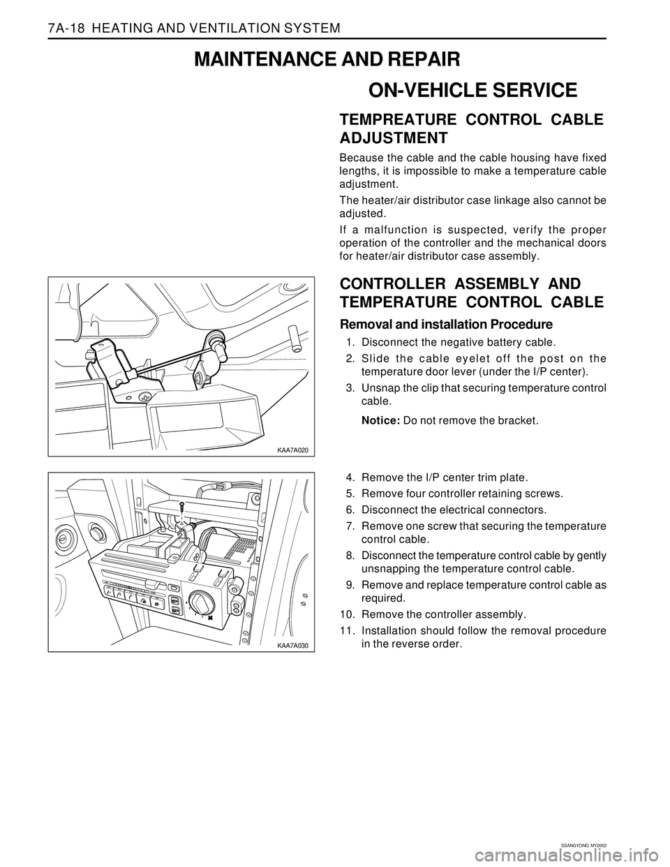
CONTROLLER ASSEMBLY AND
TEMPERATURE CONTROL CABLE
Removal and installation Procedure
1. Disconnect the negative battery cable.
2. Slide the cable eyelet off the post on the
temperature door lever (under the I/P center).
3. Unsnap the clip that securing temperature control
cable.
Notice: Do not remove the bracket.
4. Remove the I/P center trim plate.
5. Remove four controller retaining screws.
6. Disconnect the electrical connectors.
7. Remove one screw that securing the temperature
control cable.
8. Disconnect the temperature control cable by gently
unsnapping the temperature control cable.
9. Remove and replace temperature control cable as
required.
10. Remove the controller assembly.
11. Installation should follow the removal procedure
in the reverse order.