1997 SSANGYONG KORANDO service
[x] Cancel search: servicePage 986 of 2053

EBCM Connection Fact View.............................4E-95
EBCM Connector...............................................4E-95
Hydraulic Modulator Connector..........................4E-96
Repair Instructions..............................................4E-99
On-Vehicle Service...............................................4E-99
Service Precautions...........................................4E-99
ABS 5.3 Assembly..........................................4E-100
ABS/TCS Unit..................................................4E-100
Front Wheel Speed Sensor..............................4E-101Rear Wheel Speed Sensor...............................4E-101
Acceleration Sensor .........................................4E-102
System Fuse...................................................4E-102
Indicators........................................................4E-102
Unit Repair........................................................4E-103
ABS Front Tooth Wheel....................................4E-103
Special Tools and Equipment..........................4E-104
Special Tools Table..........................................4E-104
Page 987 of 2053

ABS AND TCS 4F-3
SSANGYONG MY2002
GENERAL DESCRIPTION AND SYSTEM OPERATION
BASIC KNOWLEDGE REQUIRED
Before using this section, it is important that you have
a basic knowledge of the following items. Without this
knowledge, it will be difficult to use the diagnostic
procedures contained in this section.
•Basic Electrical Circuits - You should understand
the basic theory of electricity and know the meaning
of voltage, current (amps), and resistance (ohms).
You should understand what happens in a circuit
with an open or shorted wire. You should be able to
read and understand a wiring diagram.
Use of Circuit Testing Tools - You should know
how to use a test light and how to bypass
components to test circuits using fused jumper
wires. You should be familiar with a digital
multimeter. You should be able to measure voltage,
resistance, and current, and be familiar with the
controls and how to use them correctly.
ABS SYSTEM COMPONENTS
The ABS 5.3 Antilock Braking System (ABS) consists
of a conventional hydraulic brake system plus antilock
components. The conventional brake system includes
a vacuum booster, master cylinder, front disc brakes,
rear disc brakes, interconnecting hydraulic brake pipes
and hoses, brake fluid level switch and the BRAKE
indicator.
The ABS components include a hydraulic unit, an elec-
tronic brake control module (EBCM), two system fuses,
four wheel speed sensors (one at each wheel), intercon-
necting wiring, the ABS indicator, the EBD indicator
and the TCS indicator. See “ABS Component Locator”
in this section for the general layout of this system.
The hydraulic unit with the attached EBCM is located
between the surge tank and the bulkhead on the left
side of the vehicle.
The basic hydraulic unit configuration consists of hy-
draulic check valves, two solenoid valves for each
wheel, a hydraulic pump, and two accumulators. The
hydraulic unit controls hydraulic pressure to the front
calipers and rear calipers by modulating hydraulic
pressure to prevent wheel lockup.
Units equipped with TCS add two more valves for each
drive wheel for the purpose of applying the brake to a
wheel that is slipping. This is done with pressure from
the hydraulic pump in the unit. There is also a TCS
indicator lamp on the instrument panel to alert the driver
to the fact that the TCS system is active. The
components identified in the drawing are those added
to the basic ABS 5.3 system to provide traction control.
Nothing in the hydraulic unit or the EBCM is serviceable.
In the event of any failure, the entire ABS unit withattached EBCM must be replaced. For more
information, refer to “Base Braking Mode” and
“Antilock Braking Mode” in this section.
TRACTION CONTROL SYSTEM
(TCS) DESCRIPTION
General Information
The traction control system (TCS) is a traction system
by means of brake intervention only, available in a low
speed range (< 60kph).
It workes on µ - split roads with sidewise different friction
coefficients.
The spinning driven wheel is braked and the drive
torque can be transferred to the wheel on the high-µ
side. During TCS active, the TCS information lamp is
blinking.
The temperature of the brakes is calculated by a mathe-
matical model and TCS is switched passive if the calcu-
lated temperature is greater than a threshold value (500
°C).
TCS is permitted again, when the calculated tempera-
ture is less than 350 °C.
Control Algorithm
The input signals for the control algorithm are the
filtered wheel speed signals from the ABS speed
processing.
With the speed difference of the driven wheels, the
control deviation is calculated.
If the control deviation exceeds a certain threshold
value, the wheel with the greater slip is braked actively.
The threshold value depends on the vehicle speed:
It is reduced with increasing vehicle speed down to a
constant value.
KAA4F010
Page 989 of 2053

ABS AND TCS 4F-5
SSANGYONG MY2002
EBD (ELECTRONIC BRAKE
FORCE DISTRIBUTION) SYSTEM
System Description
As an add-on logic to the ABS base algorithm, EBD
works in a range in which the intervention thresholds
for ABS control are not reached yet.
EBD ensures that the rear wheels are sensitively
monitored for slip with respect to the front axle. If slip
is detected, the inlet valves for the rear wheels are
switched to pressure hold to prevent a further increase
in pressure at the rear-wheel breaks, thus electronically
reproducing a pressure-reduction function at the rear-
wheel brakes.
ABS features an enhanced algorithm which includes
control of the brake force distribution between the front
and rear axles. This is called Electronic Brake
Distribution. In an unloading car condition the brake
efficiency is comparable to the conventional system
but for a fully loaden vehicle the efficiency of the EBD
system is higher due to the better use of rear axle
braking capability.
The Benefits of EBD
Elimination of conventional proportioning valve EBD
utilizes the existing rear axle wheel speed sensor
to monitor rear wheel slip.
Based on many variables in algorithm a pressure
hold, increase and/or decrease pulsetrain may be
triggered at the rear wheels insuring vehicle
stability.
Vehicle approaches the ideal brake force
distribution (front to rear).
Constant brake force distribution during vehicle
lifetime.
EBD function is monitored via ABS safety logic
(conventional proportioning valves are not
monitorable).
“Keep alive” function.Service Precautions
Observe the following general precautions during any
ABS/TCS service. Failure to adhere to these
precautions may result in ABS/TCS system damage.
1. Disconnect the EBCM harness connector before
performing the electric welding procedures.
2. Carefully note the routing of the ABS/TCS wiring
and wring components during removal. The ABS/
TCS components are extremely sensitive to EMI
(eletromagnetic interference). Proper mounting is
critical during component service.
3. Disconnect the EBCM connector with the ignition
OFF.
4. Do not hang the suspension components from the
wheel speed sensor cables. The cables may be
damaged.
5. Do not use petroleum based fluids in the master
cylinder. Do not use any containers previously used
for petroleum based fluids. Petroleum causes
swelling and distortion of the rubber components
in the hydraulic brake system, resulting in water
entering the system and lowering the fluid boiling
point.
KAA4F020
Page 998 of 2053

ABS AND TCS 4F-15
SSANGYONG MY2002
DIAGNOSIS
KAA4F110
DIAGNOSTIC CIRCUIT CHECK
The Diagnostic Circuit Check is an organized approach
to identifying a problem created by an antilock brake
system (ABS) malfunction. If must be the starting point
for any ABS complaint diagnosis because it directs
the service technician to the next logical step in
diagnosing the complaint.
Diagnostic Process
Perform the following steps in order when servicing
the ABS/TCS system. Failure to do so may result in
the loss of important diagnostic data and may lead to
difficulties and time-consuming diagnosis procedures.
1. Perform the tests of the table below.2. Perform a road test if directed by the table.
Test drive the vehicle while using the snapshot
feature of the scan tool.
Perform normal acceleration, stopping, and
turning maneuvers.
If this does not reproduce the malfunction,
perform an ABS stop or TCS maneuver on a low
friction surface such as gravel.
3. Clear the diagnostic trouble codes (DTCs) after
all system malfunctions have been corrected.
Page 1082 of 2053

ABS AND TCS 4F-99
SSANGYONG MY2002
REPAIR INSTRUCTIONS
ON-VEHICLE SERVICE
SERVICE PRECAUTIONS
Caution: Brake Fluid may irritate eyes and skin. In
case of contact, take the following actions:
Eye contact - rinse thoroughly with water.
Skin contact - wash with soap and water.
Ingestion - consult a physician immediately.
Caution: To help avoid personal injury due to poor
braking. DO NOT Tap into the vehicle’s brake system
to operate a trailer brake system.
Notice: When fasteners are removed, always reinstall
them at the same location from which they were
removed. If a fastener needs to be replaced, use the
correct part number fastener for is not available, a
fastener of equal size and strength (or stronger) may
be used. Fasteners that are not reused, and those
requiring thread-locking compound will be called out.
The correct torque values must be used when installing
fasteners that require them. If the above procedures
are not followed, parts or system damage could result.
Notice: Use only DOT-3 equivalent hydraulic brake
fluid. The use of DOT-5 (silicone) brake fluid is not
recommended. Reduced brake performance or
durability may result.
Notice: Avoid spilling brake fluid on any the vehicle’s
painted surfaces, wiring, cables or electrical
connectors. Brake fluid will damage paint and electrical
connections. If any fluid is spilled on the vehicle, flush
the area with water to lessen the damage.
Electronic System Service Precautions
Take care to avoid electronic brake control module
(EBCM) circuit overloading. In testing for opens or
shorts, do not ground or apply voltage to any circuit
unless instructed to do so by the diagnostic procedure.
Test circuits only with a high-impedance multi-meter.
Never remove or apply power to any control module
with the ignition switch in the ON position. Always turn
the ignition to the OFF position before removing or
connecting battery cables, fuses or connectors.
General Service Precautions
Disconnect the EBCM connector before performing any
vehicle welding work using an electric arc welder.
Do not attempt to disassemble any component
designated as nonserviceable. The hydraulic modulator
and the EBCM can be separated from each other and
replaced separately but cannot be serviced. They have
no replaceable parts, and there is no replaceable parts,
and there is no access to the components they contain.
Bleeding System
Replacement modulators are shipped already filled
and bled. In normal procedures requiring removal of
the modulator, such as to replace the EBCM, air will
not enter the modulator, and normal bleeding will be
all that is needed.
If air enters the hydraulic modulator, or if an unfilled
modulator is installed, use the brake bleeding program
in the scan tool to bleed the modulator. Manual
bleeding of the hydraulic modulator is not possible.
Page 1088 of 2053

SECTION 4G
PARKING BRAKE
TABLE OF CONTENTS
Description and Operation..................................4G-2
Brake Caliper......................................................4G-2
Component Locator.............................................4G-3
Repair Instructions...............................................4G-4
On-Vehicle Service................................................4G-4Parking Brake Adjustment - Rear Disc Brakes.....4G-4
Parking Brake Lever............................................4G-5
Parking Brake Cable...........................................4G-6
Specifications......................................................4G-7
Fastener Tightening Specifications......................4G-7
Page 1091 of 2053

SSANGYONG MY2002
4G-4 PARKING BRAKE
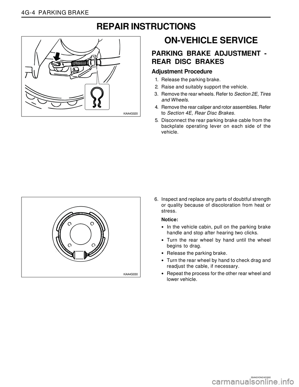
KAA4G020
KAA4G030
6. Inspect and replace any parts of doubtful strength
or quality because of discoloration from heat or
stress.
Notice:
In the vehicle cabin, pull on the parking brake
handle and stop after hearing two clicks.
Turn the rear wheel by hand until the wheel
begins to drag.
Release the parking brake.
Turn the rear wheel by hand to check drag and
readjust the cable, if necessary.
Repeat the process for the other rear wheel and
lower vehicle.
ON-VEHICLE SERVICE
PARKING BRAKE ADJUSTMENT -
REAR DISC BRAKES
Adjustment Procedure
1. Release the parking brake.
2. Raise and suitably support the vehicle.
3. Remove the rear wheels. Refer to Section 2E, Tires
and Wheels.
4. Remove the rear caliper and rotor assemblies. Refer
to Section 4E, Rear Disc Brakes.
5. Disconnect the rear parking brake cable from the
backplate operating lever on each side of the
vehicle.
REPAIR INSTRUCTIONS
Page 1095 of 2053

SECTION 5A
AUTOMATIC TRANSMISSION
CAUTION: Disconnect the negative battery cable before removing or installing any electrical unit or when a
tool or equipment could easily come in contact with exposed electrical terminals. Disconnecting this cable
will help prevent personal injury and damage to the vehicle. The ignition must also be in LOCK unless
otherwise noted.
TABLE OF CONTENTS
Description and Operation . . . . . . . . . . . . . . . . . 5A-2
BTRA M74 4WD Automatic Transmission . . . . . . 5A-2
Operators Interfaces . . . . . . . . . . . . . . . . . . . . . 5A-2
Control Systems . . . . . . . . . . . . . . . . . . . . . . . . 5A-3
Electronic Control System . . . . . . . . . . . . . . . . . 5A-3
Hydraulic Control System . . . . . . . . . . . . . . . . . . 5A-9
Hydraulic Control Circuit . . . . . . . . . . . . . . . . . . 5A-10
Power Train System . . . . . . . . . . . . . . . . . . . . . 5A-14
Power Flows . . . . . . . . . . . . . . . . . . . . . . . . . . 5A-18
Park and Neutral . . . . . . . . . . . . . . . . . . . . . . . 5A-20
Reverse . . . . . . . . . . . . . . . . . . . . . . . . . . . . . . 5A-22
Manual 1 . . . . . . . . . . . . . . . . . . . . . . . . . . . . . 5A-24
Drive 1 . . . . . . . . . . . . . . . . . . . . . . . . . . . . . . 5A-26
Drive 2 and Manual 2 . . . . . . . . . . . . . . . . . . . . 5A-28
Drive 3 and Manual 3 . . . . . . . . . . . . . . . . . . . . 5A-30
Drive 3 Lock Up and Manual 3 Lock Up . . . . . . 5A-32
Drive 4 (Overdrive) . . . . . . . . . . . . . . . . . . . . . 5A-34
Drive 4 Lock Up . . . . . . . . . . . . . . . . . . . . . . . . 5A-36
Diagnostic Information and Procedures . . . . . 5A-38
Diagnosis . . . . . . . . . . . . . . . . . . . . . . . . . . . . . 5A-38
Basic Knowledge Required . . . . . . . . . . . . . . . 5A-38
Functional Check Procedure . . . . . . . . . . . . . . . 5A-38
Transmission Fluid Level Service Procedure . . . 5A-38
Fluid Leak Diagnosis and Repair . . . . . . . . . . . 5A-39
Electrical / Garage Shift Test . . . . . . . . . . . . . . 5A-40
Road Test Procedure . . . . . . . . . . . . . . . . . . . . 5A-40
Electronic Adjustments . . . . . . . . . . . . . . . . . . 5A-40
Symptom Diagnosis . . . . . . . . . . . . . . . . . . . . . 5A-41
Drive Faults . . . . . . . . . . . . . . . . . . . . . . . . . . . 5A-41
Faulty Shift Pattern . . . . . . . . . . . . . . . . . . . . . . 5A-42Shift Quality Faults . . . . . . . . . . . . . . . . . . . . . . 5A-44
After Teardown Faults . . . . . . . . . . . . . . . . . . . 5A-46
Trouble Code Diagnosis - Gasoline Vehicle . . 5A-48
TCM Diagnostic System Overview . . . . . . . . . . 5A-48
Clearing Trouble Codes . . . . . . . . . . . . . . . . . . 5A-48
Diagnostic Trouble Codes . . . . . . . . . . . . . . . . 5A-48
Trouble Code Diagnosis - Diesel Vehicle . . . . . 5A-50
TCM Diagnostic System Overview . . . . . . . . . . 5A-50
Clearing Trouble Codes . . . . . . . . . . . . . . . . . . 5A-50
Diagnostic Trouble Codes . . . . . . . . . . . . . . . . 5A-50
Repair Instructions . . . . . . . . . . . . . . . . . . . . . . 5A-157
On-Vehicle Service . . . . . . . . . . . . . . . . . . . . . . . 5A-157
Transmission . . . . . . . . . . . . . . . . . . . . . . . . . . 5A-157
Unit Repair . . . . . . . . . . . . . . . . . . . . . . . . . . . . 5A-160
Rebuild Warnings . . . . . . . . . . . . . . . . . . . . . . 5A-160
Disassembly Procedure . . . . . . . . . . . . . . . . . . 5A-161
Assembly Procedure . . . . . . . . . . . . . . . . . . . . 5A-171
Front and Rear Band Adjustment . . . . . . . . . . . 5A-199
Gear Shift Control Lever . . . . . . . . . . . . . . . . . . 5A-202
Kickdown Switch . . . . . . . . . . . . . . . . . . . . . . . 5A-202
Specifications . . . . . . . . . . . . . . . . . . . . . . . . . . 5A-203
General Specification . . . . . . . . . . . . . . . . . . . . 5A-203
Fastener Tightening Specifications . . . . . . . . . . 5A-205
Schematic and Routing Diagrams . . . . . . . . . . 5A-206
TCM Wiring Diagrams (Gasoline Engine) . . . . . 5A-206
TCM Wiring Diagrams (Diesel Engine) . . . . . . . 5A-208
Connector End View . . . . . . . . . . . . . . . . . . . . . 5A-210
Special Tools and Equipment . . . . . . . . . . . . . 5A-211
Special Tools Table . . . . . . . . . . . . . . . . . . . . . 5A-211