Page 665 of 2053

1B3 -- 116 OM600 ENGINE MECHANICAL
D AEW OO M Y_2000
CHECK AND REPLACEMENT OF VALVE GUIDES
Preceding Work : Removal of cylinder head
Removal of valve spring
Removal of valve
1 Cylinder Head
2 Valve Guide3 Valve Seat Ring
a Basic Bore Diameter
Service Ddata
������������������������ �
����������������������� ������������������������
�����������������������������������
����������������������������������� �����������������������������������Item
��������������������������������������������� �
�������������������������������������������� ���������������������������������������������Outer Diameter
’D’
��������������������������������� �
�������������������������������� ���������������������������������Color Code
����������������������������������������� �
���������������������������������������� �����������������������������������������Basic Bore
Diameter ’a’
���������������������������� �
��������������������������� ����������������������������Overlap
’D’ -- ’a’
������������������������������������������ �
����������������������������������������� ������������������������������������������Valve Guide
InnerDiameter’A’
���������������������� �
��������������������� ����������������������Length
’L’
IntakeRepair size 114.251Red14.200 -- 14.2110.029 --80008030395IntakeRepair size 214.440 -- 14.451White14.400 -- 14.411
0.029--
0.0518.000 -- 8.03039.5
ExhaustRepair size 114.240 -- 14. 251Red14.200 -- 14.2110.029 --90009050377ExhaustRepair size 214.440-- 14.451White14.400 -- 14.411
0.029--
0.0519.000 -- 9.05037.7
Page 671 of 2053

1B3 -- 122 OM600 ENGINE MECHANICAL
D AEW OO M Y_2000
VALVE SEAT RINGS
Preceding Work : Removal of valve
Checking of valve guide, replace if necessary
Removal of prechamber
1 Cylinder Head
2 Valve Seat Ring
3 Valve Guide
A Height (Cylinder Head Upper / Lower Surface)
B Height (cylinder Head Cover Surface -- Seat of
Valve Seat Ring)D Valve Seat Ring Outer Diameter
D1 Valve Seat Ring Inner Diameter
D2 Basic Bore Diameter
H Height of Valve Seat Ring
Service Ddata��������������������������������������������������������������������������������������� �
�������������������������������������������������������������������������������������� ���������������������������������������������������������������������������������������
Item
��������������������������������������������������������������������������������������� �
�������������������������������������������������������������������������������������� ���������������������������������������������������������������������������������������
Intake
��������������������������������������������������������������������������������������� �
�������������������������������������������������������������������������������������� ���������������������������������������������������������������������������������������
Exhaust
D240.000 -- 40.016 mm37.000 -- 37.016 mm
D40.084 -- 40.100 mm37.084 -- 37.100 mm
D133.400 -- 33.600 mm30.400 -- 30.600 mm
H6.955 -- 7.045 mm6.955 -- 7.045 mm
Overlap U=D-- D20.068 -- 0.100 mm0.068 -- 0.100 mm
B133.4 mm133.4 mm
A142.5 mm142.5 mm
Page 678 of 2053
OM600 ENGINE MECHANICAL 1B3 -- 129
D AEW OO M Y_2000
Tools Required
001 589 32 21 00 Dial Gauge
Commercial Tool
Valve corn grinding machine
Checking and Machining
1. Clean the valves and do visual check.
Valves with wobbled valve disc, with worn or scored
valve stem should be replaced.
2. Measure valve disc height ’h’.
ServicedataIntake1.7±0.15 mmServicedataExhaust1.7±0.15 mm
3. Machine the valve.
Notice
Pay attention to setting angle ’a’.
4. Measure radial runout between valve stem and
valve seat.
LimitMax. 0.03 mm
Dial Gauge 001 589 32 21 00
Page 682 of 2053

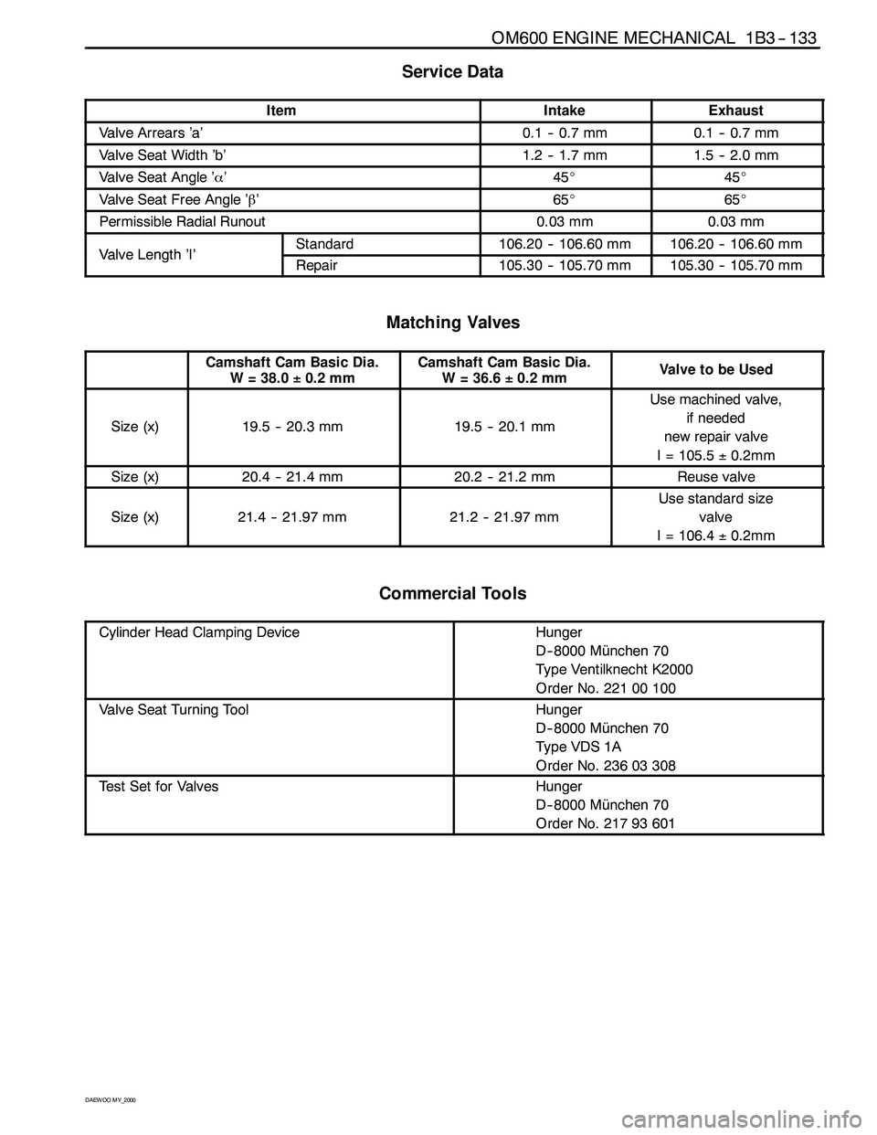
OM600 ENGINE MECHANICAL 1B3 -- 133
D AEW OO M Y_2000
Service Data
ItemIntakeExhaust
Valve Arrears ’a’0.1 -- 0.7 mm0.1 -- 0.7 mm
Valve Seat Width ’b’1.2 -- 1.7 mm1.5 -- 2.0 mm
Valve Seat Angle ’α’45_45_
Valve Seat Free Angle ’β’65_65_
Permissible Radial Runout0.03 mm0.03 mm
ValveLength’I’Standard106.20 -- 106.60 mm106.20 -- 106.60 mmValveLength’I’Repair105.30 -- 105.70 mm105.30 -- 105.70 mm
Matching Valves
Camshaft Cam Basic Dia.
W = 38.0±0.2 mmCamshaft Cam Basic Dia.
W=36.6±0.2 mmValvetobeUsed
Size (x)19.5 -- 20.3 mm19.5 -- 20.1 mm
Use machined valve,
if needed
new repair valve
I = 105.5±0.2mm
Size (x)20.4 -- 21.4 mm20.2 -- 21.2 mmReuse valve
Size (x)21.4 -- 21.97 mm21.2 -- 21.97 mm
Use standard size
valve
I = 106.4±0.2mm
Commercial Tools
Cylinder Head Clamping DeviceHunger
D-- 8000 München 70
Type Ventilknecht K2000
Order No. 221 00 100
Valve Seat Turning ToolHunger
D-- 8000 München 70
Ty p e VDS 1 A
Order No. 236 03 308
Test Set for ValvesHunger
D-- 8000 München 70
Order No. 217 93 601
Page 713 of 2053
1B3 -- 164 OM600 ENGINE MECHANICAL
D AEW OO M Y_2000
Service Data
Piston clearanceMax. 0.12 mm
Piston crown protrusion in TDC position0.735 -- 0.965 mm
Connecting rod bushing diameter26.012 -- 26.018 mm
Connecting Rod Bolt Dimensions
ThreadM9 x 1
Stretch shaft(C) diameter (new)7.4-0.1mm
Minimum stretch shaft diameter (C)7.1 mm
Length(L)(new)52-0.3mm
Tools Required
000 589 04 14 00 Tensioning Strap
001 589 53 21 00 Dial Gauge
363 589 02 21 00 Dial Gauge Holder
Page 727 of 2053
1B3 -- 178 OM600 ENGINE MECHANICAL
D AEW OO M Y_2000
FACING CYLINDER HEAD MATING SURFACE
Preceding Work : Removal of prechamber
Cylinder head pressure leakage test
1Valve
2 Cylinder Head
3 Prechamber
A Height of Cylinder HeadB Longitudinal Direction
C Transverse Direction
a Valve Arrears
b Prechamber Protrusion
Service Data
Height ’A’
(cylinder head surface -- cylinder head cover surface)142.9 -- 143.1 mm
Minimum height after machining142.5 mm
PermissibleunevennessofpartingsurfaceIn longitudinal direction0.08 mmPermissible unevenness of parting surfaceIn transverse direction0.0 mm
Permissible variation of parallelism (longitud. Direction)Max. 0.1 mm
Peak -- to-- valley height0.0017 mm
Vl’’Intake valve0.1 -- 0.7 mmValve arrears ’a’Exhaust valve0.1 -- 0.7 mm
Prechamber protrusion7.6 -- 8.1 mm
Page 731 of 2053
1B3 -- 182 OM600 ENGINE MECHANICAL
D AEW OO M Y_2000
FACING CRANKCASE CONTACTING SURFACE
1 Crankcase
2 Crankcase Contacting Surface
Y Height (crankcase upper surface -- crankcase
lower surface)B Longitudinal Direction
C Transverse Direction
H Chamfer Height
b Chamfer Angle
Service Data
Height ’Y’Min. 299.62 mm
PermissibleunevennessofcontactingsurfaceIn longitudinal direction (B)0.06 mmPermissible unevenness of contacting surfaceIn transverse direction (C)0.06 mm
Permissible roughness upper contacting surface0.0006 -- 0.0016 mm
Permissible variation of parallelism of crankcase upper
surface to lower surface in longitudinal direction0.05 mm
PittitTDCtkfMax.0.965 mmPiston protrusion at TDC to crankcase upper surfaceMin.0.735 mm
Page 736 of 2053
OM600 ENGINE MECHANICAL 1B3 -- 187
D AEW OO M Y_2000
CYLINDER BORE MEASUREMENT
a Longitudinal Direction
b Transverse Direction
c, d, e. Measuring Point
1 Crankcase Contacting Surface
2 TDC of 1st Piston Ring
4 BDC of Ring
Service Data
Code letter ’A’89.000 -- 89.006mm
Standard sizeCode letter ’X’89.006 -- 89.012mmStandardsize
Code letter ’B’89.012 -- 89.018mm
WearlimitindirectionoftravelandintransversedirectionMax. 0.20mmWear limit in direction of travel and in transverse directionWhen new0.01mm
Permissible deviation of cylinder shapeWear limit0.05mm
Honing angle50_±10_