Page 333 of 2053
1B2 -- 40 M161 ENGINE MECHANICAL
D AEW OO M Y_2000
Components
1 Center Bolt (M18 x 50)
2 Center Bolt Washer
3 Vibration Damper and Pulley Assembly
4Key
5 Crankshaft Front Seal
6 Timing Gear Case Cover7 Crankshaft Sprocket (Camshaft Driven)
8 Crankshaft Sprocket (Oil pump Driven)
9 Crankshaft
10 Oil Pan
11 Oil Pan Gasket
12 Oil Pan Mounting Bolt (M6 x 22)
ServiceDataStandard
Permissble Deviation of The Vibration DamperRadial Runout0.6 mmp
Axial Runout0.6 mm
Page 340 of 2053

M161 ENGINE MECHANICAL 1B2 -- 47
D AEW OO M Y_2000
Color Dot
MarkingCrankshaft Journal Diameter
(mm)
Blue57.960 -- 57.965
Yellow57.955 -- 57.960
Red57.950 -- 57.955
White57.945 -- 57.950
Violet57.940 -- 57.945
Selection of Crankshaft Main Bearing
1. Crankcase Side
There are seven punching marks on the mating sur-
face to oil pan. This mark is correspondent to the
bearing distinguished by color. Select the relevant
bearing according to the punching mark when re-
paired.
Punching
Mark
Bearing Color Selected
FBlue
FFYellow
FFFRed
2. Crankshaft Bearing Cap Side
Select the crankshaft main bearing according to the
marking letter on the crankshaft main journal when
repaired.
Marking
Letter
Bearing Color Selected
BBlue
YYellow
RRed
WWhite
VViolet
Service DataUnit: mm
Crankshaft Stan-
dard and Repair
SizeCrankshaft
Bearing Jour-
nal DiameterCrankshaft
Bearing
DiameterCrankshaft
Journal Width
at fit bearingConnecting Rod
Bearing Journal
DiameterConnecting Rod
Bearing Journal
Width
Standard size57.940-- 57.9655824.50-- 24.53347.935-- 47.96527.958-- 28.042
1st repair size57.705-- 57.71547.700-- 47.715
2nd repair size57.450-- 57.46547.450-- 47.465
3rd repair size57.205-- 57.215----47.200-- 47.215--
4th repair size56.955-- 56.96546.950-- 46.965
Page 343 of 2053
1B2 -- 50 M161 ENGINE MECHANICAL
D AEW OO M Y_2000
Service Data Standard (Crankshaft Main Bearing Gap)
ItemMeasuring PositionGap (mm)
Main Bearing Journal
(NO.1,5,7)
Radial
Static condition : 0.015 -- 0.039
Dynamic condition: 0.031 -- 0.051
(Consider the expansion 0.011 -- 0.016)
(NO.1,5,7)
Axial0.010 -- 0.254
(Connecting Rod Bearing Gap)
ItemMeasuring PositionGap (mm)
Connecting Rod BearingRadial0.020 -- 0.065
Page 344 of 2053
M161 ENGINE MECHANICAL 1B2 -- 51
D AEW OO M Y_2000
FLYWHEEL / DRIVEN PLATE
Preceding Work: Removal of manual or automatic transmission
1 Flywheel Mounting Bolt (M10 x 22, 8 pieces)
1st step 45+5 NSm (33+3.7 lb-ft) ............
2nd step 90°+10°
2Plate3 Driven Plate (A/T)
4 Dowel Pin
5 Flywheel (M/T)
Service Data Standard (Stretch Bolt)
Nominal SizeD--Mx1.5
Stretch Side DiameterdWhen New8.5 -- 0.2 mm
Min. Diameter8.0 mm
Bolt LengthLWhen New21.8 -- 22.2 mm
Tightening Torque1ststep45+5NSm (33 + 3.7 lb-ft), 2nd step 90°+10°
Page 379 of 2053

1B2 -- 86 M161 ENGINE MECHANICAL
D AEW OO M Y_2000
CONNECTING ROD
Preceding Work: Removal of piston
1 Connecting Rod Bushing
2 Oil Gallery
3 Balance Weight
4 Connecting Rod Bearing Cap Bolt
(M9 x 52, 8 pieces)
1ststep40NSm (30 lb-ft) ..................
2nd step 90°5 Fit Sleeve
6 Upper Connecting Rod Bearing
7 Lower Connecting Rod Bearing
8 Bearing Shell Lug
9 Marking [Indication (//) or Numbers]
ServiceDataStandard
Distance (L) from The Connecting Rod Bearing to Bushing Bore CenterE20 : 154 mm
E23 : 149±0.05 mm
Width of The Connecting Rod (B) at Bearing Bore21.940 -- 22.000 mm
Width of The Connecting Rod (b) at Bushing Bore21.940 -- 22.000 mm
Basic Bore at The Bearing Shell (D1)51.600 -- 51.614 mm
Basic Bore at The Bushing (d1)24.500 -- 24.521 mm
Bushing Inner Diameter (d)22.007 -- 22.013 mm
Clearance Between The Piston Pin and The Bushing0.007 -- 0.018 mm
Peak -- to-- valley Height of Connecting Rod Bushing on Inside0.005 mm
Permissible Wwist of Connecting Rod Bearing Bore to Connecting Rod Bushing
Bore0.1/100 mm
Permissible Deviation of Axial Paralleism of Connecting Rod
Bearing Bore to Connecting Rod Bushing Bore0.045/100 mm
Permissible Deviation of Axial Paralleism of Connecting Rod Bearing Bore from
Concentricity0.01 mm
Permissible Difference of Each Connecting Rod in Weight0.4 g
Page 391 of 2053

M161 ENGINE MECHANICAL 1B2 -- 103
D AEW OO M Y_2000
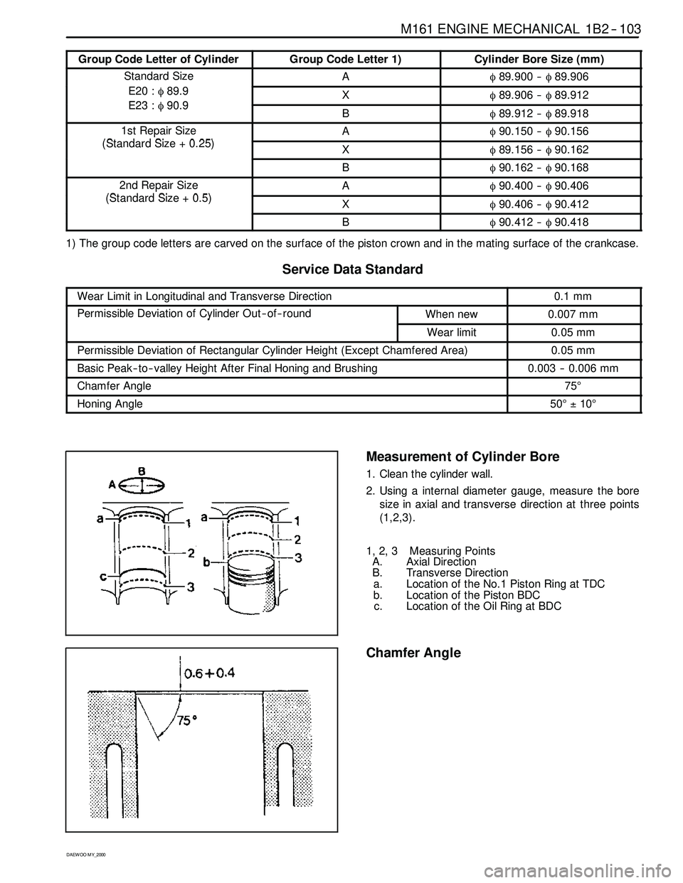
Group Code Letter of CylinderGroup Code Letter 1)Cylinder Bore Size (mm)
Standard SizeAφ89.900 --φ89.906
E20 :φ89.9
E23φ909Xφ89.906 --φ89.912E23 :φ90.9Bφ89.912 --φ89.918
1st Repair Size
(StddSi025)
Aφ90.150 --φ90.156p
(Standard Size + 0.25)Xφ89.156 --φ90.162
Bφ90.162 --φ90.168
2nd Repair Size
(StddSi05)
Aφ90.400 --φ90.406p
(Standard Size + 0.5)Xφ90.406 --φ90.412
Bφ90.412 --φ90.418
1) The group code letters are carved on the surface of the piston crown and in the mating surface of the crankcase.
ServiceDataStandard
Wear Limit in Longitudinal and Transverse Direction0.1 mm
Permissible Deviation of Cylinder Out -- of -- roundWhen new0.007 mmy
Wear limit0.05 mm
Permissible Deviation of Rectangular Cylinder Height (Except Chamfered Area)0.05 mm
Basic Peak -- to-- valley Height After Final Honing and Brushing0.003 -- 0.006 mm
Chamfer Angle75°
Honing Angle50°±10°
Measurement of Cylinder Bore
1. Clean the cylinder wall.
2. Using a internal diameter gauge, measure the bore
size in axial and transverse direction at three points
(1,2,3).
1, 2, 3 Measuring Points
A. Axial Direction
B. Transverse Direction
a. Location of the No.1 Piston Ring at TDC
b. Location of the Piston BDC
c. Location of the Oil Ring at BDC
Chamfer Angle
Page 392 of 2053
1B2 -- 104 M161 ENGINE MECHANICAL
D AEW OO M Y_2000
CRANKCASE MATING SURFACE
ServiceDataStandard
Height of The Crankcase ‘H’ (When new)289.35 -- 289.45 mm
Minimum Height After Milling289.05 mm
FlatnessCrankcase Upper Mating Surface0.03 mm
Crankcase Lower Mating Surface0.04 mm
Permissible Deviation of Parallelism of The
UtLMtiSf
Axial Direction0.1 mm
Upper to Lower Mating SurfaceTransverse Direction0.05 mm
Peak -- to-- valley HeightCrankcase Upper Mating Surface0.012 -- 0.009 mmyg
Crankcase Lower Mating Surface0.025 -- 0.020 mm
Page 394 of 2053
1B2 -- 106 M161 ENGINE MECHANICAL
D AEW OO M Y_2000
CYLINDER HEAD MATING SURFACE
Preceding Work: Removal of valves
ServiceDataStandard
Overall Height of Cylinder Head135.9 -- 136.0 mm
Minimum Height After Machining135.5 mm
FlatnessAxial Direction0.08 mm
Transverse Direction0.0 mm
Distance ‘T’
(BtChftBi
Standard SizeIntake24.21 -- 24.75 mm
(Between Camshaft Bearing
andValveStem)Exhaust22.21 -- 22.75 mmandValveStem)
Repair SizeIntake23.96 -- 24.51 mmp
Exhaust21.96 -- 22.51 mm
Notice:Do not exceed 0.4mm for the milling of the mating surface of crankcase and cylinder head.