Page 1008 of 1503
Brake Hoses/Lines
Inspection
1. Inspect the brake hoses for damage, deterioration, leaks, interference or twisting.
2. Check the brake lines for damage, rusting and leakage. Also check for bent brake lines.
3. Check for leaks at hose and line joints or connections, and retighten if necessary.
4. Check the master cylinder and ABS modulator unit for damage and leakage.
CAUTION: Replace the brake hose clip whenever the brake hose is serviced.ProCarManuals.com
Page 1040 of 1503
6. Installatio n is th e revers e o f remova l procedure .
NOTE : Afte r installation , star t th e engin e an d mak e
sur e tha t th e AB S indicato r ligh t goe s off .
4
. Remov e th e fou r contro l uni t attachin g bolts , the n
remov e th e bracke t wit h th e contro l unit .
5 . Remov e th e AB S contro l uni t fro m th e bracket .
2 . Mov e th e heate r duc t t o th e righ t an d remov e it .
SR
S component s ar e locate d in thi s area . Revie w th e SR S
componen t locations , precautions , an d procedure s i n th e
SR S sectio n 24 befor e performin g repair s o r service .
1 . Remov e th e dashboar d lowe r cove r an d glov e box ,
an d disconnec t th e ligh t connector . 3
. Disconnec t th e connector s fro m th e AB S contro l uni t
b y removin g th e wir e harnes s band .
ABS Contro l Uni t Replacemen t
Electronic Component s
ProCarManuals.com
Page 1047 of 1503

Construction and Function (cont'd)
System Description
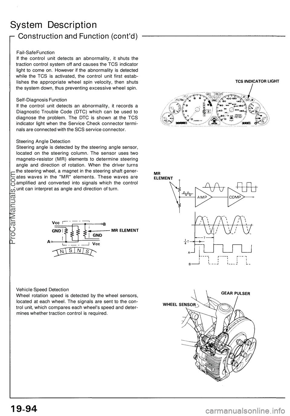
Fail-Safe Function
If the control unit detects an abnormality, it shuts the
traction control system off and causes the TCS indicator
light to come on. However if the abnormality is detected
while the TCS is activated, the control unit first estab-
lishes the appropriate wheel spin velocity, then shuts
the system down, thus preventing excessive wheel spin.
Self-Diagnosis Function
If the control unit detects an abnormality, it records a
Diagnostic Trouble Code (DTC) which can be used to
diagnose the problem. The DTC is shown at the TCS
indicator light when the Service Check connector termi-
nals are connected with the SCS service connector.
Steering Angle Detection
Steering angle is detected by the steering angle sensor,
located on the steering column. The sensor uses two
magneto-resistor (MR) elements to determine steering
angle and direction of rotation. When the driver turns
the steering wheel, a magnet in the steering shaft gener-
ates waves in the "MR" elements. These waves are
amplified and converted into signals which the control
unit can interpret as angle and direction of turn.
Vehicle Speed Detection
Wheel rotation speed is detected by the wheel sensors,
located at each wheel. The signals are sent to the con-
trol unit, which compares each wheel's speed and deter-
mines whether traction control is required.ProCarManuals.com
Page 1052 of 1503

NOTE:
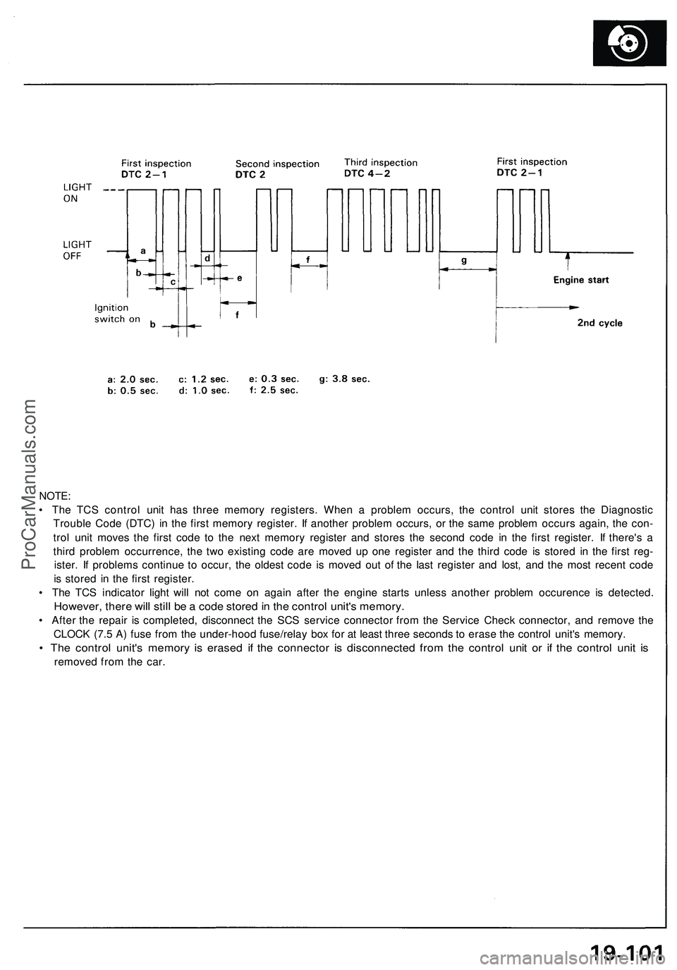
• The TCS control unit has three memory registers. When a problem occurs, the control unit stores the Diagnostic
Trouble Code (DTC) in the first memory register. If another problem occurs, or the same problem occurs again, the con-
trol unit moves the first code to the next memory register and stores the second code in the first register. If there's a
third problem occurrence, the two existing code are moved up one register and the third code is stored in the first reg-
ister. If problems continue to occur, the oldest code is moved out of the last register and lost, and the most recent code
is stored in the first register.
• The TCS indicator light will not come on again after the engine starts unless another problem occurence is detected.
However, there will still be a code stored in the control unit's memory.
• After the repair is completed, disconnect the SCS service connector from the Service Check connector, and remove the
CLOCK (7.5 A) fuse from the under-hood fuse/relay box for at least three seconds to erase the control unit's memory.
• The control unit's memory is erased if the connector is disconnected from the control unit or if the control unit is
removed from the car.ProCarManuals.com
Page 1106 of 1503
Carpet
Replacemen t
SRS component s ar e locate d in thi s area . Revie w th e SR S componen t locations , precautions , an d procedure s i n th e SR S
( sectio n 24 ) befor e performin g repair s o r service .
1 . Remove :
• Seat s (se e pag e 20-39 )
• Footres t
• Under-das h fus e bo x li d (se e pag e 20-38 )
• Sid e sil l tri m (se e pag e 20-38 ) •
Sid e sil l pa d (se e pag e 20-38 )
• Rea r sid e tri m pane l (se e pag e 20-38 )
• Cente r armres t (se e pag e 20-49 )
• Cente r consol e pane l (se e pag e 20-52 )
2. Detac h th e clip s a t th e fron t edg e (passenger's) .
3. Remov e th e consol e carpe t attachin g scre w fro m th e heate r uni t (passenger's) .
4 . Disconnec t th e ai r duc t (driver's ) an d ai r vent , the n remov e th e carpe t hook s fro m th e dashboar d insid e screws .
DASHBOAR D
INSID E SCRE W
CARPE THOOK(3)
AI R VEN T
CLIPS
CONSOL E CARPE T
FLOORCARPE T
SRS UNI TSCRE W
CONSOL ECARPET
AIR DUC T
AIR VEN T
ProCarManuals.com
Page 1111 of 1503
Dashboard
Componen t Removal/Installatio n (cont'd )
SRS component s ar e locate d in thi s area . Revie w th e SR S componen t locations , precautions , an d procedure s in th e SR S
( sectio n 24 ) befor e performin g repair s o r service .
Cente r consol e pane l removal :
NOTE:
• Tak e car e no t t o scratc h th e dashboard , cente r consol e pane l an d relate d parts .
• D o no t dro p th e screw s insid e th e dashboard .
• Remov e th e cente r armres t (se e pag e 20-49 ), cloc k an d cente r ai r ven t (se e pag e 20-50 ).
Disassembl e i n numbere d sequence .
ASHTRAY
CENTER CONSOL EPANEL
Disconnec t th econnectors .
SRS UNI T
Lift u p th e parkin gbrake lever .
Installatio n i s th e revers e of the remova l procedure .
NOTE : Mak e sur e th e connector s ar e connecte d properly .
ProCarManuals.com
Page 1113 of 1503
Dashboard
Componen t Removal/Installatio n (cont'd )
SRS component s ar e locate d in thi s area . Revie w th e SR S componen t locations , precautions , an d procedure s in th e SR S
(sectio n 24 ) befor e performin g repair s o r service .
NOTE: Tak e car e no t t o scratc h th e dashboard ,
steerin g colum n an d relate d parts .
CAUTION : Whe n pryin g wit h a fla t ti p screw -
driver , wra p it wit h protectiv e tap e o r a sho p towe l
t o preven t damage .
Drivers:
RETRACTO R SWITCH /
DAS H BRIGHTNES S
CONTROLLE R
Disconnect th e
connectors .
DASHBOAR D LOWE R
COVE R (Driver's )
Installation i s th e revers e of the remova l procedure .
NOTE : Mak e sur e th e connector s ar e connecte d properly .
Disconnec t th e connectors .
DASHBOAR DLOWER PA D
DASHBOAR DLOWER PA D
DASHBOAR DBRACE
INSTRUMEN TPANEL
CLIP
INSTRUMEN TPANEL
TCS SWITC H
ProCarManuals.com
Page 1114 of 1503

Replacement
SRS component s ar e locate d in thi s area . Revie w th e SR S
componen t locations , precautions , an d procedure s i n th e
SR S ( sectio n 24 ) befor e performin g repair s o r service .
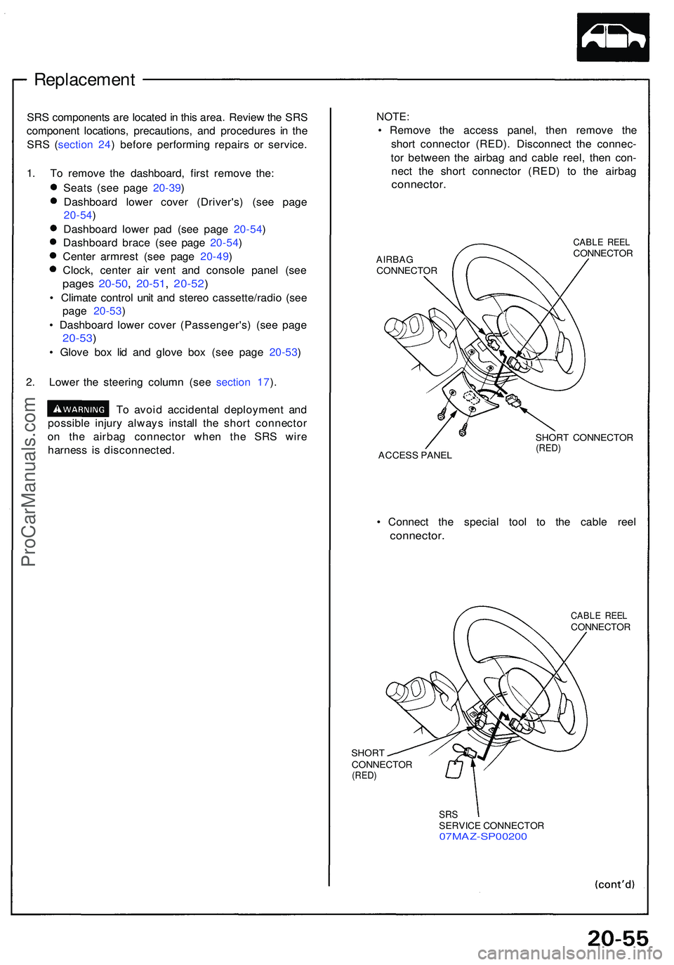
1 . T o remov e th e dashboard , firs t remov e the :
Seat s (se e pag e 20-39 )
Dashboar d lowe r cove r (Driver's ) (se e pag e
20-54 )
Dashboar d lowe r pa d (se e pag e 20-54 )
Dashboar d brac e (se e pag e 20-54 )
Cente r armres t (se e pag e 20-49 )
Clock , cente r ai r ven t an d consol e pane l (se e
page s 20-50 , 20-51 , 20-52 )
• Climat e contro l uni t an d stere o cassette/radi o (se e
pag e 20-53 )
• Dashboar d lowe r cove r (Passenger's ) (se e pag e
20-53 )
• Glov e bo x li d an d glov e bo x (se e pag e 20-53 )
2 . Lowe r th e steerin g colum n (se e sectio n 17 ).
T o avoi d accidenta l deploymen t an d
possibl e injur y alway s instal l th e shor t connecto r
o n th e airba g connecto r whe n th e SR S wir e
harnes s i s disconnected .
NOTE:
• Remov e th e acces s panel , the n remov e th e
shor t connecto r (RED) . Disconnec t th e connec -
to r betwee n th e airba g an d cabl e reel , the n con -
nec t th e shor t connecto r (RED ) t o th e airba g
connector .
AIRBAGCONNECTO R
CABLE REE LCONNECTO R
ACCES S PANE L SHOR
T CONNECTO R
(RED)
• Connec t th e specia l too l t o th e cabl e ree l
connector .
SHORT
CONNECTO R
(RED)
CABL E REE LCONNECTO R
SRSSERVIC E CONNECTO R07MAZ-SP0020 0
ProCarManuals.com