Page 1228 of 1503

A/C Syste m Servic e
Leak Tes t
Only us e servic e equipmen t tha t i s U.L.-liste d an d is cer -
tifie d t o mee t th e requirement s o f SA E J221 0 t o remov e
HFC-134 a (R-134a ) fro m th e ai r conditionin g system .
CAUTION : Exposur e t o ai r conditione r refrigeran t
an d lubrican t vapo r o r mis t ca n irritat e eyes , nos e
an d throat . Avoi d breathin g th e ai r conditione r
refrigeran t an d lubrican t vapo r o r mist .
I f accidenta l syste m discharg e occurs , ventilat e wor k
are a befor e resumin g service .
R-134a servic e equipmen t o r vehicl e ai r conditionin g sys -
tem shoul d no t b e pressur e teste d o r lea k teste d wit h
compresse d air .
Som e mixture s o f ai r an d R-134 a hav e
bee n show n to b e combustibl e a t elevate d pressure s
an d ca n resul t i n fir e o r explosio n causin g injur y o r
propert y damage . Neve r us e compresse d ai r t o pres -
sur e tes t R-134 a servic e equipmen t o r vehicl e ai r
conditione r systems.
Additiona l healt h an d safet y informatio n ma y b e obtaine d
fro m th e refrigeran t an d lubrican t manufacturers .
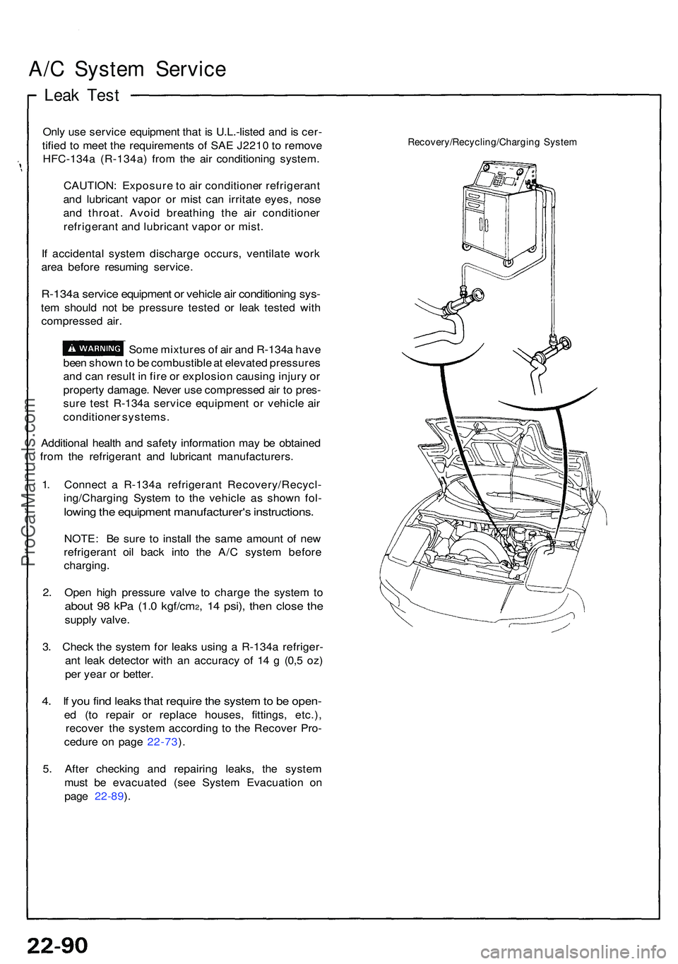
1 . Connec t a R-134 a refrigeran t Recovery/Recycl -
ing/Chargin g Syste m to th e vehicl e a s show n fol -
lowin g th e equipmen t manufacturer' s instructions .
NOTE: B e sur e t o instal l th e sam e amoun t o f ne w
refrigeran t oi l bac k int o th e A/ C syste m befor e
charging .
2 . Ope n hig h pressur e valv e t o charg e th e syste m to
abou t 9 8 kP a (1. 0 kgf/cm2, 1 4 psi) , the n clos e th e
suppl y valve .
3 . Chec k th e syste m fo r leak s usin g a R-134 a refriger -
an t lea k detecto r wit h a n accurac y o f 1 4 g (0, 5 oz )
pe r yea r o r better .
4. I f yo u fin d leak s tha t requir e th e syste m to b e open -
ed (t o repai r o r replac e houses , fittings , etc.) ,
recove r th e syste m accordin g t o th e Recove r Pro -
cedur e o n pag e 22-73 ).
5 . Afte r checkin g an d repairin g leaks , th e syste m
mus t b e evacuate d (se e Syste m Evacuatio n o n
pag e 22-89 ).
Recovery/Recycling/Chargin g Syste m
ProCarManuals.com
Page 1229 of 1503
Charging
Only use service equipment that is U.L.-listed and is
certified to meet the requirements of SAE J2210 to
remove HFC-134a (R-134a) from the air conditioner
system.
CAUTION: Exposure to air conditioner refrigerant
and lubricant vapor or mist can irritate eyes, nose
and throat. Avoid breathing the air conditioner
refrigerant and lubricant vapor or mist.
If accidental system discharge occurs, ventilate work
area before resuming service. Additional health and safe-
ty information may be obtained from the refrigerant and
lubricant manufacturers.
Refrigerant capacity: 850
CAUTION: Do not overcharge the system; the
compressor will be damaged.
Connect a R-134a refrigerant Recovery/Recycling/
Charging System to the vehicle as shown follow the
equipment manufacturer's instructions.
Recovery/Recycling/Charging SystemProCarManuals.com
Page 1243 of 1503
Under-dash Fus e Bo x
Removal/Installatio n
SRS component s ar e locate d in thi s area . Revie w th e SR S
componen t locations , precautions , an d procedure s in th e
SR S ( sectio n 24 ) befor e performin g repair s o r service .
Removal :
1. Disconnec t bot h th e negativ e cabl e an d positiv e
cabl e fro m th e battery .
2 . Carefull y remov e th e sid e sil l pa d (pul l i t up , rea r
en d first) .
3 . Remov e th e fus e bo x door .
FUSE BO XDOO R
SIDE SIL L PA D
SIDE SIL L TRI M
4. Remov e th e thre e screws , the n remov e th e sid e sil l
trim .
5. Remov e th e under-das h fus e bo x mountin g bolts . 6
. Disconnec t th e under-das h fus e bo x connectors .
NOTE : Th e SR S mai n harnes s connecto r i s doubl e
locked . T o remov e it , firs t lif t th e connecto r lid ,
the n pres s th e connecto r ta b dow n an d pul l th e
connecto r out .
LIDTA B
SRS MAI N HARNES S
7. Tak e ou t th e under-das h fus e box .
ProCarManuals.com
Page 1246 of 1503
Steering Loc k Removal/Installatio n
SRS component s ar e locate d in thi s area . Revie w th e SR S
componen t locations , precautions , an d procedure s in th e
SR S (sectio n 24 ) befor e performin g repair s o r service .
1 . Remov e th e dashboar d lowe r cover , an d disconnec t
the connectors .
2. Remov e th e dashboar d lowe r pad .
DASHBOAR D LOWE R
COVE R
3. Remov e the tilt cover .
DASHBOAR D LOWE RPAD
TIL T COVE R
4. Remov e th e steerin g colum n lowe r an d uppe r cov -
ers. B e carefu l no t t o damag e th e steerin g colum n
covers .
UPPER COVE R
LOWE R COVE R
5. Remov e th e dashboar d brace .
DASHBOAR D BRAC E
6. Disconnec t th e ignitio n switc h 7 P an d 8 P connec -
tors.
7. Remov e th e colum n holde r mountin g bolt s an d th e
mountin g nuts , an d lowe r th e steerin g colum n
assembly . B e carefu l no t t o damag e th e SR S wir e
harness .
16 N- m(1.6 kgf-m , 1 2 Ibf-ft )
.39 N- m(4.0 kgf-m , 2 9 Ibf-ft )
(cont'd )
ProCarManuals.com
Page 1262 of 1503

Ignition Timin g Inspectio n
SRS component s ar e locate d in thi s area . Revie w th e SR S
componen t locations , precautions , an d procedure s i n th e
SR S (sectio n 24 ) befor e performin g repair s o r service .
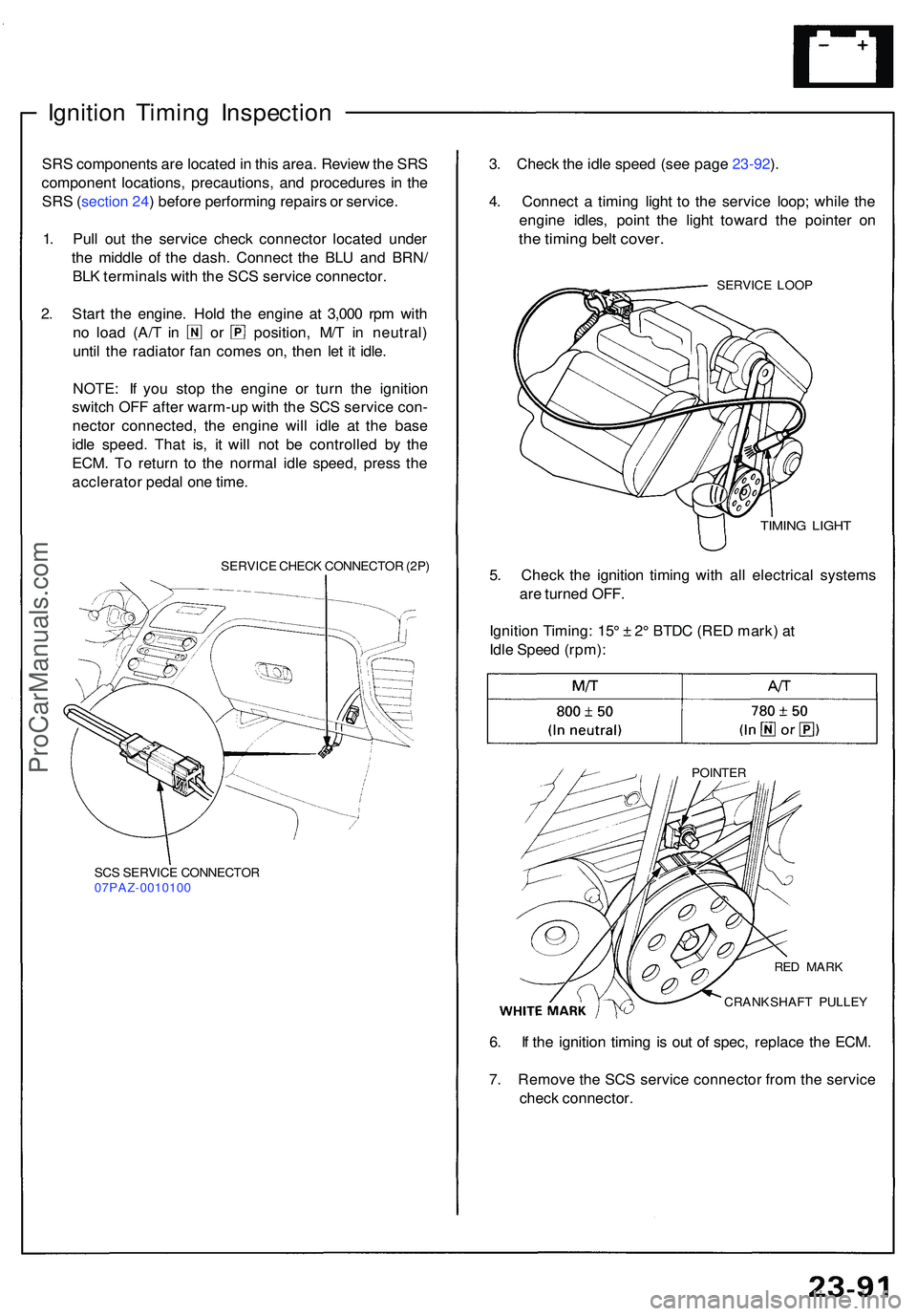
1 . Pul l ou t th e servic e chec k connecto r locate d unde r
th e middl e o f th e dash . Connec t th e BL U an d BRN /
BL K terminal s wit h th e SC S servic e connector .
2 . Star t th e engine . Hol d th e engin e a t 3,00 0 rp m wit h
no loa d (A/ T i n o r position , M/ T i n neutral )
unti l th e radiato r fa n come s on , the n le t i t idle .
NOTE : I f yo u sto p th e engin e o r tur n th e ignitio n
switc h OF F afte r warm-u p wit h th e SC S servic e con -
necto r connected , th e engin e wil l idl e a t th e bas e
idl e speed . Tha t is , i t wil l no t b e controlle d b y th e
ECM . T o retur n t o th e norma l idl e speed , pres s th e
acclerato r peda l on e time .
SERVIC E CHEC K CONNECTO R (2P )
SC S SERVIC E CONNECTO R
07PAZ-001010 0
3. Chec k th e idl e spee d (se e pag e 23-92 ).
4 . Connec t a timin g ligh t t o th e servic e loop ; whil e th e
engin e idles , poin t th e ligh t towar d th e pointe r o n
the timin g bel t cover .
SERVIC E LOO P
TIMIN G LIGH T
5. Chec k th e ignitio n timin g wit h al l electrica l system s
ar e turne d OFF .
Ignitio n Timing : 15 ° ± 2° BTD C (RE D mark ) a t
Idl e Spee d (rpm) :
POINTE R
6. I f th e ignitio n timin g i s ou t o f spec , replac e th e ECM .
7 . Remov e th e SC S servic e connecto r fro m th e servic e
chec k connector .
CRANKSHAF T PULLE Y
RE
D MAR K
ProCarManuals.com
Page 1277 of 1503

Rectifier Test
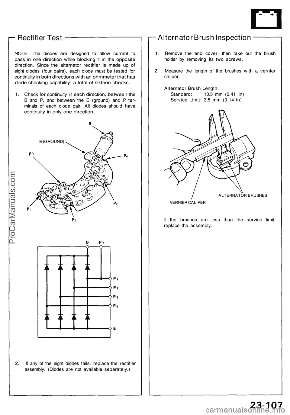
NOTE: The diodes are designed to allow current to
pass in one direction while blocking it in the opposite
direction. Since the alternator rectifier is made up of
eight diodes (four pairs), each diode must be tested for
continuity in both directions with an ohmmeter that has
diode checking capability; a total of sixteen checks.
1. Check for continuity in each direction, between the
B and P, and between the E (ground) and P ter-
minals of each diode pair. All diodes should have
continuity in only one direction.
E (GROUND)
2. If any of the eight diodes fails, replace the rectifier
assembly. (Diodes are not available separately.)
Alternator Brush Inspection
1. Remove the end cover, then take out the brush
holder by removing its two screws.
2. Measure the length of the brushes with a vernier
caliper.
Alternator Brush Length:
Standard: 10.5 mm (0.41 in)
Service Limit: 3.5 mm (0.14 in)
ALTERNATOR BRUSHES
VERNIER CALIPER
If the brushes are less than the service limit,
replace the assembly.ProCarManuals.com
Page 1289 of 1503
Gauge Assembl y
Gauge/Terminal Location Index
SRS component s ar e locate d in thi s area . Revie w th e SR S componen t locations , precautions , an d procedure s in th e SR S
(sectio n 24 ) befor e performin g repair s o r service .
SPEEDOMETER :Indicates 6 0 mp h [60km/h ] a t 1.02 6 [637 ]
rp m o f th e vehicl e spee d senso r (VSS) .
FUE L GAUGE :
• Gaug e test , pag e 23-13 4
• Sendin g Uni t Test , pag e 23-13 5
VOLTAG E METER :
If, wit h th e No . 5 (1 5 A ) fus eand othe r gauge s
OK , th e pointe r o f th e
voltag e mete r doe s
no t mov e a t all ,
replac e th e voltag e
meter .
TACHOMETER :Indicates 10 0 rp m a t 30 0 pulse s pe r minut eof th e ignite r unit .
COOLAN T TEMPERATUR E GAUGE :• Gaug e Test , pag e 23-13 6
• Sende r Test , pag e 23-13 6
SAFET Y INDICATO R SYSTEM :
Se e pag e 23-156 ENGIN
E OI L PRESSUR E
GAUGE:Test pag e 23-13 7
A/ T GEA R POSITIO N
INDICATO R SYSTE M
Se e pag e 23-158
ProCarManuals.com
Page 1290 of 1503
Gauge Assembl y
Removal
SRS component s ar e locate d in thi s area . Revie w th e SR S
componen t locations , precautions , an d procedure s in th e
SR S ( sectio n 24 ) befor e performin g repair s o r service .
1 . Remov e th e dashboar d lowe r cover , an d disconnec t
th e floo r wir e harnes s connectors .
2 . Remov e th e tw o screws , the n remov e th e dashboar d
lowe r pa d fro m th e dashboard .
DASHBOAR DLOWERCOVER
DASHBOAR DLOWER PA D 3
. Remov e th e thre e screws , the n remov e th e til t cove r
fro m th e steerin g column .
TILT COVE R
4. Disconnec t th e connector s fro m th e instrumen t
panel switches .
5 . Remov e th e si x screws , the n remov e th e instrumen t
pane l tri m fro m th e dashboard .
INSTRUMEN T PANE L TRI M
ProCarManuals.com