Page 770 of 1503

Road Tes t
positio n
SR S component s ar e locate d in thi s area . Revie w th e SR S componen t locations , precautions , an d procedure s i n th e SR S
( sectio n 24 ) befor e performin g repair s o r service .
1 . Appl y parkin g brak e an d bloc k th e wheels . Star t th e engine , an d war m u p th e engin e t o norma l operatin g temperatur e
(th e coolin g fa n come s on) . (Whe n th e engin e coolan t temperatur e i s belo w norma l operatin g temperature , th e shif t
point i s highe r tha n specifie d vehicl e speed. ) Shif t t o positio n whil e depressin g th e brak e pedal . Depres s th e acceler -
ato r pedal , an d releas e it suddenly . Th e engin e shoul d no t stall .
2 . Chec k tha t th e shif t point s o n a fla t roa d occu r a t th e approximat e speed s show n o n th e nex t page . Als o chec k fo r
abnorma l nois e an d clutc h slippage .
NOTE : Throttl e positio n senso r voltag e represent s th e throttl e opening .
-1 . Remov e th e sea t bac k panel s (se e sectio n 20 ).
-2 . Remov e th e connecto r holde r fro m th e TC S contro l unit , an d disconnec t th e antenn a lead . The n remov e th e TC S
contro l uni t (se e pag e 14-52 ).
NOTE : D o no t disconnec t th e TC S contro l uni t connectors .
-3 . Remov e th e TC M an d tur n it over .
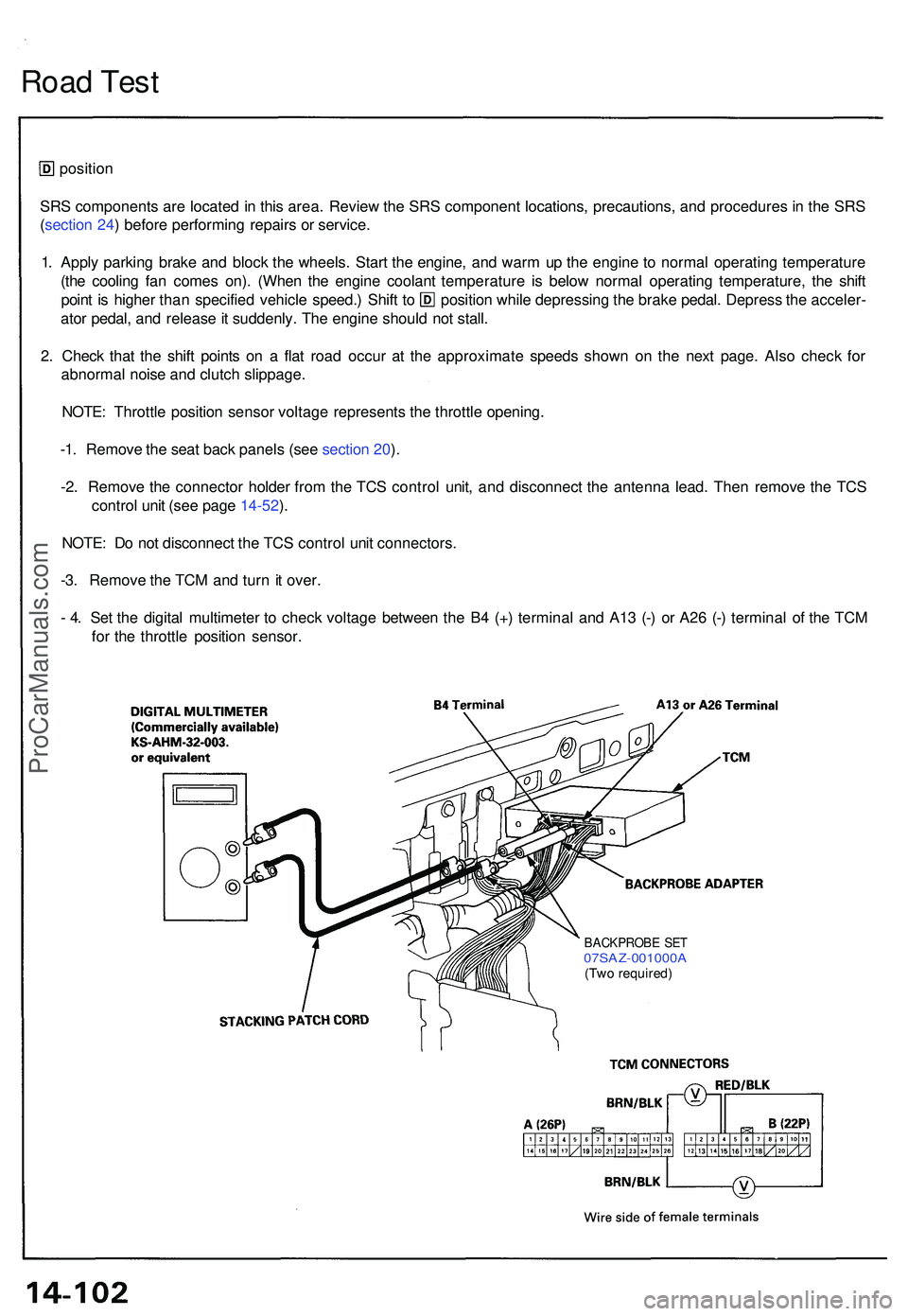
- 4 . Se t th e digita l multimete r t o chec k voltag e betwee n th e B 4 (+ ) termina l an d A1 3 (- ) o r A2 6 (- ) termina l o f th e TC M
fo r th e throttl e positio n sensor .
BACKPROB E SE T07SAZ-001000 A(Two required )
ProCarManuals.com
Page 822 of 1503
14. Measure the clearance between the clutch end plate
and top disc with a dial indicator. Zero the dial indi-
cator with the clutch end plate lowered, and lift it up
to the snap ring. The distance that the clutch end
plate moves is the clearance between the clutch end
plate and top disc.
NOTE: Measure at three locations.
End Plate-to-Top Disc Clearance:
Reassembly (cont'd)
Clutch
15. If the clearance is not within the service limits, select
a new clutch end plate from the following table.
NOTE: If the thickest clutch end plate is installed,
but the clearance is still over the standard, replace
the clutch discs and clutch plates.
CLUTCH END PLATE
2ND, 3RD, 4TH and 1ST-HOLD CLUTCH:
1ST CLUTCH:ProCarManuals.com
Page 840 of 1503
Shift Cabl e
Removal/Installatio n
SRS component s ar e locate d i n thi s area . Revie w th e SR S componen t locations , precautions , an d procedure s i n th e SR S
( sectio n 24 ) befor e performin g repair s o r service .
Make sur e lift s ar e place d properl y (se e sectio n 1 ).
1 . Remov e th e cente r consol e pane l (se e sectio n 20 ).
2 . Remov e th e shif t cabl e b y removin g th e cotte r pi n an d shif t leve r pi n fro m th e shif t lever . Remov e th e mountin g bolt s
fro m th e bracke t beam .
3 . Remov e th e shif t cabl e clamp .
4 . Remov e th e shif t cabl e holde r an d shif t cabl e cover .
5 . Remov e th e shif t cabl e b y removin g th e loc k pi n an d contro l leve r pi n fro m th e contro l lever .
CAUTION : Tak e car e n o to ben d th e cabl e whe n removin g it .
6. Instal l th e shif t cabl e in th e revers e orde r o f removal .
7. Afte r installation , chec k th e cabl e adjustmen t (se e pag e 14-171 ).
ProCarManuals.com
Page 841 of 1503
SRS component s ar e locate d i n thi s area . Revie w th e SR S componen t locations , precautions , an d procedure s i n th e SR S
( sectio n 24 ) befor e performin g repair s o r service .
Shift Leve r
ProCarManuals.com
Page 892 of 1503
Component Location s
Index
NOTE :
• I f a n intac t airba g assembl y ha s bee n remove d fro m a scrappe d vehicl e o r ha s bee n foun d defectiv e o r damage d durin g
transit , storag e o r service , i t shoul d b e deploye d (se e sectio n 24 ).
• Befor e removin g th e gearbox , remov e th e ignitio n ke y t o loc k th e steerin g shaft .
• Afte r installin g th e gearbox , chec k th e whee l alignmen t an d adjus t i f necessary .
STEERING GEARBO XRemoval/Installation , pag e 17-5 3
Illustrate d Index , pag e 17-5 7
Pinio n Preloa d Inspection , pag e 17-5 8
Rac k Guid e Scre w Adjustment , pag e 17-5 8
STEERIN
G COLUM N
Removal , pag e 17-4 7
Inspection , pag e 17-4 9
Installation , pag e 17-5 0
STEERIN G WHEEL /AIRBAG ASSEMBL YRemoval, pag e 17-4 3
Disassembly , pag e 17-4 4
Installation , pag e 17-4 5
EP
S CONTRO L UNI T
Replacement , pag e 17-62
ProCarManuals.com
Page 902 of 1503

Self-Diagnosis Function
The EPS control unit monitors the system inputs and outputs, and the driving current of the motor. If there is a problem in
the system, the control unit turns the system off by actuating the relay. Power assist stops and normal manual steering
operation resumes. The control unit also turns the EPS indicator light on to alert the driver, and memorizes the problem in
the form of a code. Connecting the terminals of the service check connector with the SCS service connector (special tool)
enables the EPS indicator light to blink the problem code when the ignition switch is turned on (II).
Unloader Control
If the steering wheel is turned fully and held in the full-lock position, the steering torque reaches the maximum point, and
an over-current flows to the motor. The control unit detects this and reduces the current flow to the motor.
Average Moving Current Control
The electric current flow to the motor is estimated from the current values detected by the current sensor, and the average
current is obtained at two second intervals. The motor driving current is suppressed when the average current value
exceeds a predetermined marginal value. The control unit regulates the motor current during continuous loading to sup-
press any excessive temperature rise in the motor.ProCarManuals.com
Page 910 of 1503
Diagnostic Troubl e Cod e (DTC ) Indicatio n
1. Connec t th e SC S servic e connecto r t o th e servic e chec k connecto r unde r th e glov e box .
2 . Tur n th e ignitio n switc h O N (II) , bu t d o no t star t th e engine .
3 . Recor d th e blinkin g frequenc y o f th e EP S indicato r light . Th e blinkin g frequenc y indicate s th e diagnosti c troubl e cod e
(DTC) .
NOTE : Chec k th e DT C carefull y an d recor d it . Th e memor y o f th e DT C is erase d i f th e connecto r i s disconnecte d fro m
th e EP S contro l unit .
SCS SERVIC E CONNECTO R07PAZ-001010 0
SERVICE CHEC KCONNECTO R (2P )
ProCarManuals.com
Page 916 of 1503

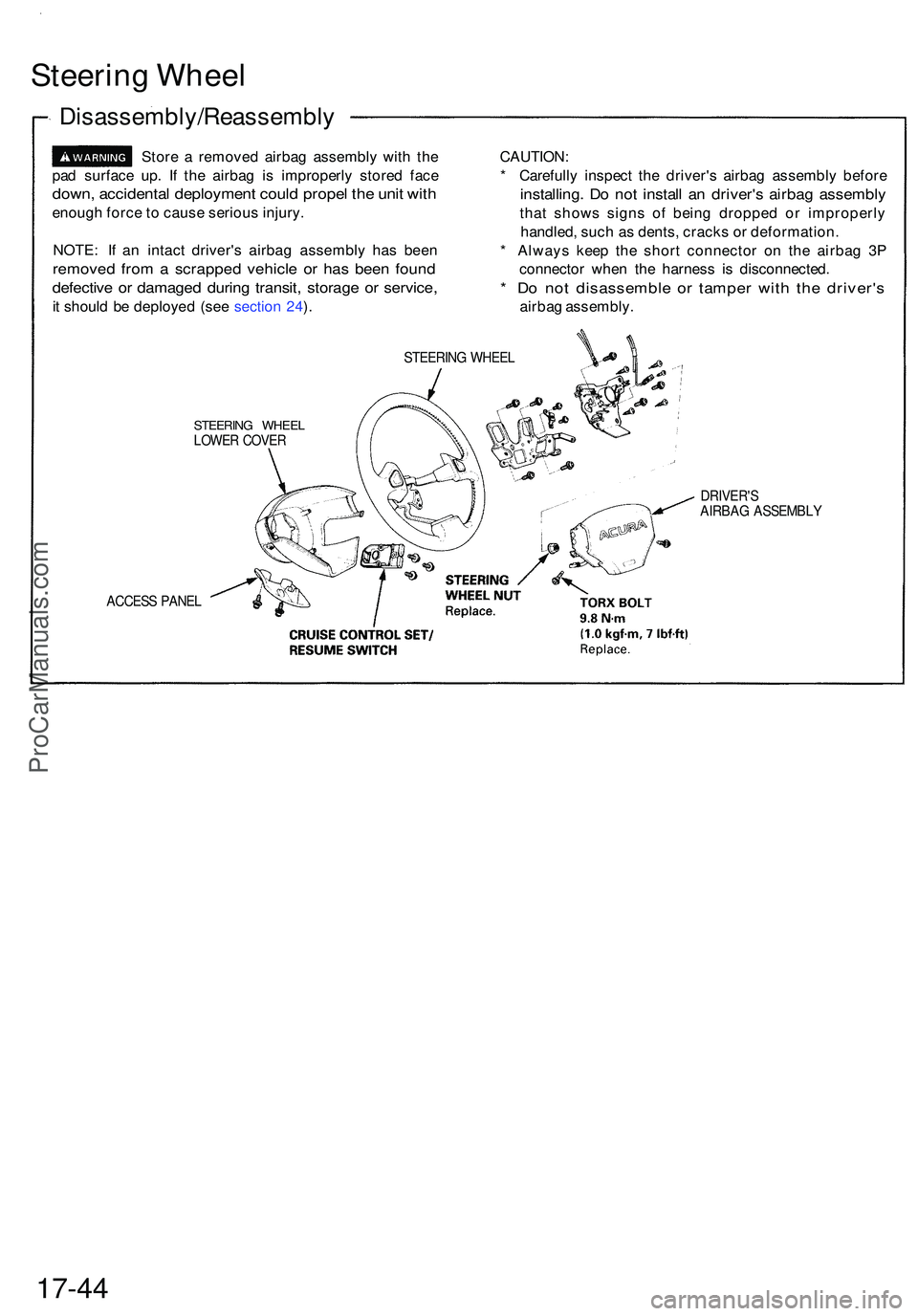
Steering Whee l
Disassembly/Reassembl y
Store a remove d airba g assembl y wit h th e
pa d surfac e up . I f th e airba g i s improperl y store d fac e
down , accidenta l deploymen t coul d prope l th e uni t wit h
enoug h forc e to caus e seriou s injury .
NOTE : I f a n intac t driver' s airba g assembl y ha s bee n
remove d fro m a scrappe d vehicl e o r ha s bee n foun d
defectiv e o r damage d durin g transit , storag e o r service ,
it shoul d b e deploye d (se e sectio n 24 ). CAUTION
:
* Carefull y inspec t th e driver' s airba g assembl y befor e
installing . D o no t instal l a n driver' s airba g assembl y
that show s sign s o f bein g droppe d o r improperl y
handled , suc h a s dents , crack s o r deformation .
* Alway s kee p th e shor t connecto r o n th e airba g 3 P
connecto r whe n th e harnes s i s disconnected .
* D o no t disassembl e o r tampe r wit h th e driver' s
airbag assembly .
STEERING WHEE L
STEERIN G WHEE LLOWER COVE R
ACCES S PANE L
DRIVER' SAIRBAG ASSEMBL Y
17-44
ProCarManuals.com