1997 ACURA NSX service
[x] Cancel search: servicePage 375 of 1503
4-6
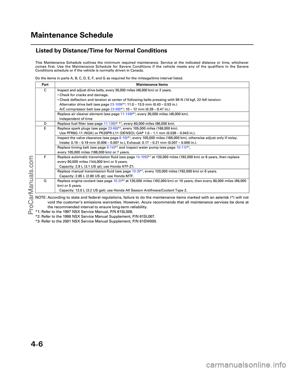
This Maintenance Schedule outlines the minimum required maintenance. Ser\
vice at the indicated distance or time, whichever
comes first. Use the Maintenance Schedule for Severe Conditions if the v\
ehicle meets any of the qualifiers in the Severe
Conditions schedule or if the vehicle is normally driven in Canada.
Do the items in parts A, B, C, D, E, F, and G as required for the mileag\
e/time interval listed.
NOTE: According to state and federal regulations, failure to do the maintenanc\
e items marked with an asterisk (*) will not
void the customer ’s emissions warranties. However, Acura recommends that all maintenance s\
ervices be done at
the recommended interval to ensure long-term reliability.
*1: Refer to the 1997 NSX Service Manual, P/N 61SL006.
*2: Refer to the 1998 NSX Service Manual Supplement, P/N 61SL007.
*3: Refer to the 2001 NSX Service Manual Supplement, P/N 61SW000.
C
D
E
F
G Inspect and adjust drive belts, every 30,000 miles (48,000 km) or 2 ye\
ars.
•
Check for cracks and damage.
• Check deflection and tension at center of following belts pressing with\
98 N (10 kgf, 22 lbf) tension:
Alternator drive belt (see page 23-109)*
1: 11.0 – 13.5 mm (0.43 – 0.53 in.)
A/C compressor belt (see page 22-88)*1: 10 – 12 mm (0.39 – 0.47 in.)
Replace air cleaner element (see page 11-149)*1, every 30,000 miles (48,000 km).
Independent of time
Replace fuel filter (see page 11-138)*, *1, every 60,000 miles (96,000 km).
Replace spark plugs (see page 23-96)*1, every 105,000 miles (168,000 km).
Use PFR6G-11 (NGK) or PK20PR-L11 (DENSO); GAP 1.0 – 1.1 mm (0.039 – 0.043 in.).
Inspect the valve clearance (see page 6-10)*1, every 105,000 miles (168,000 km), otherwise adjust only if noisy.
Intake: 0.15 – 0.19 mm (0.006 – 0.007 in.), Exhaust: 0.17 – 0.21 mm (0.007 – 0.008 in.).
Replace timing belt (see page 6-14)*1 and inspect water pump (see page 10-11)*1,
every 105,000 miles (168,000 km) or 7 years.
Replace automatic transmission fluid (see page 14-105)*1 at 120,000 miles (192,000 km) or 6 years, then replace
every 90,000 miles (144,000 km) or 5 years.
Capacity: 2.9 L (3.1 US qt); use Honda ATF-Z1.
Replace manual transmission fluid (see page 13-3)*1, every 120,000 miles (192,000 km) or 6 years.
Capacity: 2.65 L (2.80 US qt); use Honda MTF.
Replace engine coolant (see page 10-2 )*3 at 120,000 miles (192,000 km) or 10 years, then every 60,000 miles (9\
6,000
km) or 5 years. Capacity: 12.0 L (3.2 US gal); use Honda All Season Antifreeze/Coolant\
Type 2.
Part Maintenance Items
Maintenance Schedule
Listed by Distance/Time for Normal Conditions
*05-NSX (61SW004)SEC04(01-10) 9/22/04 1:49 PM Page 4-6
ProCarManuals.com
Page 384 of 1503
Towing
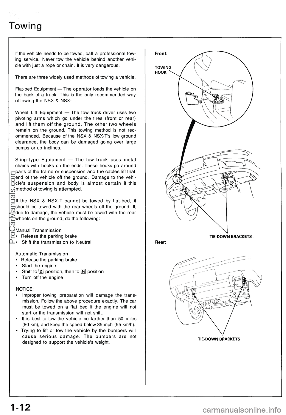
If the vehicle needs to be towed, call a professional tow-
ing service. Never tow the vehicle behind another vehi-
cle with just a rope or chain. It is very dangerous.
There are three widely used methods of towing a vehicle.
Flat-bed Equipment — The operator loads the vehicle on
the back of a truck. This is the only recommended way
of towing the NSX & NSX-T.
Wheel Lift Equipment — The tow truck driver uses two
pivoting arms which go under the tires (front or rear)
and lift them off the ground. The other two wheels
remain on the ground. This towing method is not rec-
ommended. Because of the NSX & NSX-T's low ground
clearance, the body can be damaged going over large
bumps or up inclines.
Sling-type Equipment — The tow truck uses metal
chains with hooks on the ends. These hooks go around
parts of the frame or suspension and the cables lift that
end of the vehicle off the ground. Damage to the vehi-
cle's suspension and body is almost certain if this
method of towing is attempted.
If the NSX & NSX-T cannot be towed by flat-bed, it
should be towed with the rear wheels off the ground. If,
due to damage, the vehicle must be towed with the rear
wheels on the ground, do the following:
Manual Transmission
• Release the parking brake
• Shift the transmission to Neutral
Automatic Transmission
• Release the parking brake
• Start the engine
• Shift to position, then to position
• Turn off the engine
NOTICE:
• Improper towing preparation will damage the trans-
mission. Follow the above procedure exactly. The car
must be towed on a flat bed if the engine will not
start or the transmission will not shift.
• It is best to tow the vehicle no farther than 50 miles
(80 km), and keep the speed below 35 mph (55 km/h).
• Trying to lift or tow the vehicle by the bumpers will
cause serious damage. The bumpers are not
designed to support the vehicle's weight.ProCarManuals.com
Page 385 of 1503
Service Precautions
Handling of Special Nuts and Bolts
Handling of Tires
• The tires on NSX & NSX-T should not be rotated. The
front wheels are 16" in, diameter and the rear wheels
are 17" in, so they cannot be rotated front-to-rear.
The original-equipment tires on NSX & NSX-T have a
unidirectional tread pattern, so they cannot be rotat-
ed side-to-side.
• The folding spare tire cannot be repaired or removed
from the rim.
Engine Steam-cleaning
(NSX-T only)
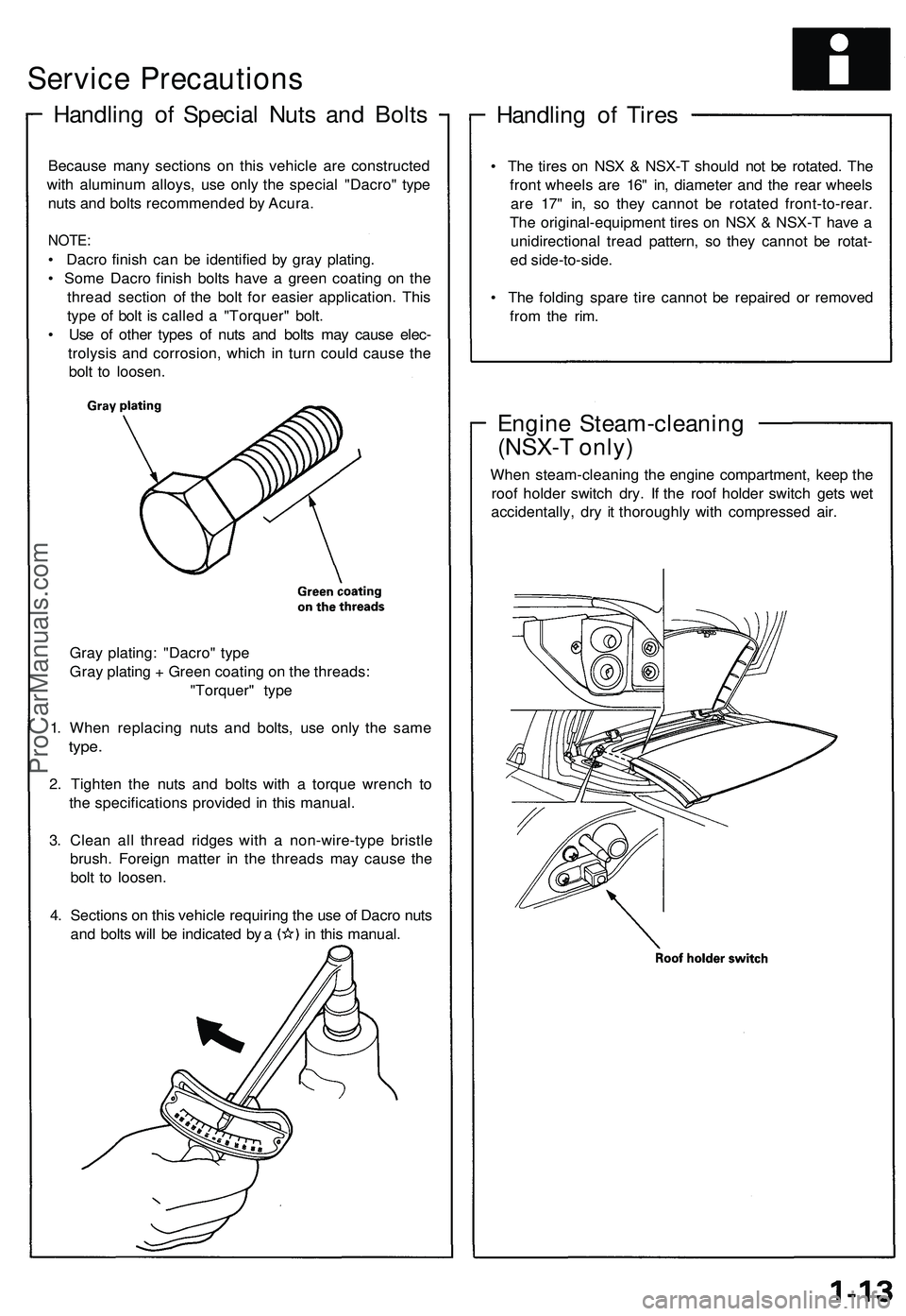
When steam-cleaning the engine compartment, keep the
roof holder switch dry. If the roof holder switch gets wet
accidentally, dry it thoroughly with compressed air.
Because many sections on this vehicle are constructed
with aluminum alloys, use only the special "Dacro" type
nuts and bolts recommended by Acura.
NOTE:
• Dacro finish can be identified by gray plating.
• Some Dacro finish bolts have a green coating on the
thread section of the bolt for easier application. This
type of bolt is called a "Torquer" bolt.
• Use of other types of nuts and bolts may cause elec-
trolysis and corrosion, which in turn could cause the
bolt to loosen.
Gray plating: "Dacro" type
Gray plating + Green coating on the threads:
"Torquer" type
1. When replacing nuts and bolts, use only the same
type.
2. Tighten the nuts and bolts with a torque wrench to
the specifications provided in this manual.
3. Clean all thread ridges with a non-wire-type bristle
brush. Foreign matter in the threads may cause the
bolt to loosen.
4. Sections on this vehicle requiring the use of Dacro nuts
and bolts will be indicated by a in this manual.ProCarManuals.com
Page 405 of 1503
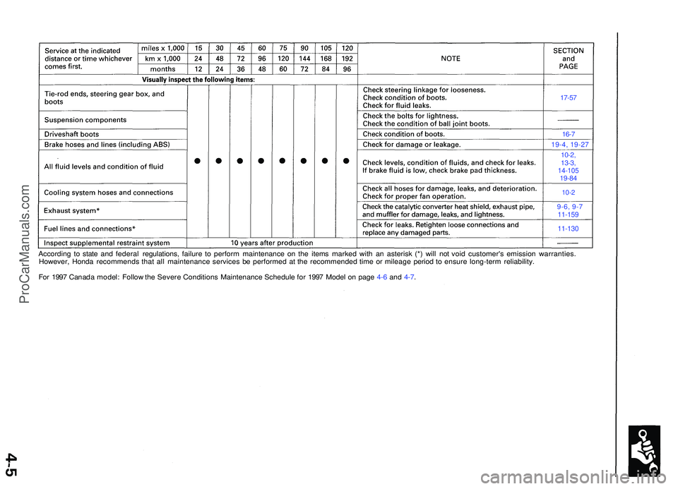
17-57
16-7
19-4, 19-2 7
10-2,
13-3 ,
14-10 519-84
10-2
9-6, 9- 711-159
11-130
Accordin g t o stat e an d federa l regulations , failur e t o perfor m maintenanc e o n th e item s marke d wit h a n asteris k (* ) wil l no t voi d customer' s emissio n warranties .
However , Hond a recommend s tha t al l maintenanc e service s b e performe d a t th e recommende d tim e o r mileag e perio d t o ensur e long-ter m reliability .
Fo r 199 7 Canad a model : Follo w th e Sever e Condition s Maintenanc e Schedule for 199 7 Mode l o n pag e 4-6 and 4-7 .
ProCarManuals.com
Page 407 of 1503
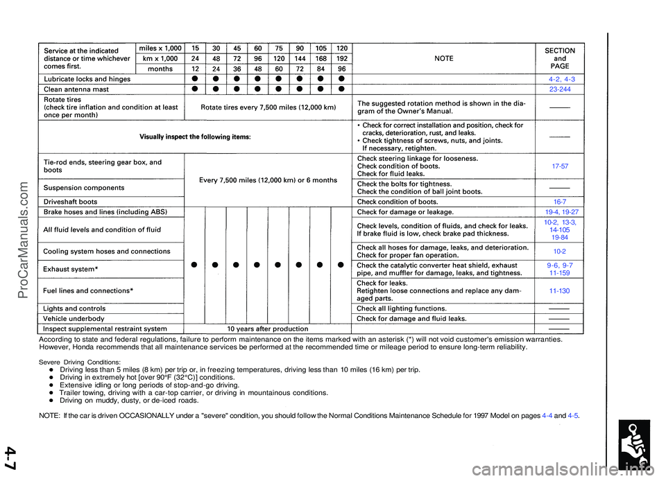
4-2, 4-3
23-244
17-57
16-7
19-4 , 19-2 7
10-2, 13-3 ,14-10 519-84
10-2
9-6, 9-711-15 9
11-130
Accordin g to stat e an d federa l regulations , failur e to perfor m maintenanc e o n th e item s marke d wit h a n asteris k (* ) wil l no t voi d customer' s emissio n warranties .
However , Hond a recommend s tha t al l maintenanc e service s b e performe d a t th e recommende d tim e o r mileag e perio d to ensur e long-ter m reliability .
Severe Drivin g Conditions :Driving les s tha n 5 mile s ( 8 km ) pe r tri p or , i n freezin g temperatures , drivin g les s tha n 1 0 mile s (1 6 km ) pe r trip .
Drivin g in extremel y ho t [ove r 90° F (32°C) ] conditions .
Extensiv e idlin g o r lon g period s o f stop-and-g o driving .
Traile r towing , drivin g wit h a car-to p carrier , o r drivin g in mountainou s conditions .
Drivin g o n muddy , dusty , o r de-ice d roads .
NOTE : I f th e ca r i s drive n OCCASIONALL Y unde r a "severe " condition , yo u shoul d follo w th e Norma l Condition s Maintenanc e Schedul e fo r 199 7 Mode l o n page s 4- 4 an d 4-5 .
ProCarManuals.com
Page 452 of 1503
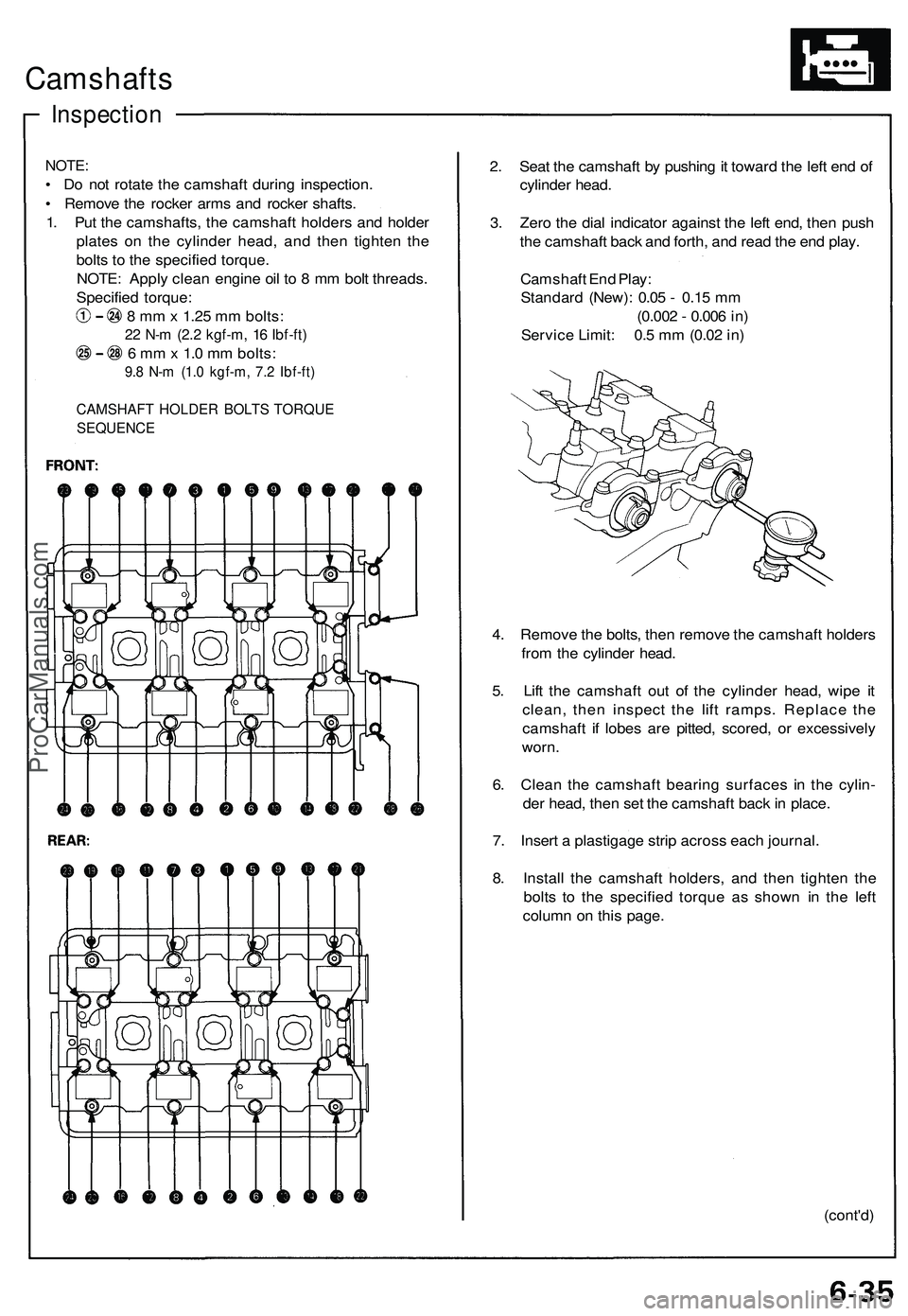
Camshafts
Inspection
NOTE:
• Do not rotate the camshaft during inspection.
• Remove the rocker arms and rocker shafts.
1. Put the camshafts, the camshaft holders and holder
plates on the cylinder head, and then tighten the
bolts to the specified torque.
NOTE: Apply clean engine oil to 8 mm bolt threads.
Specified torque:
8 mm x 1.25 mm bolts:
22 N-m (2.2 kgf-m, 16 Ibf-ft)
6 mm x 1.0 mm bolts:
9.8 N-m (1.0 kgf-m, 7.2 Ibf-ft)
CAMSHAFT HOLDER BOLTS TORQUE
SEQUENCE
2. Seat the camshaft by pushing it toward the left end of
cylinder head.
3. Zero the dial indicator against the left end, then push
the camshaft back and forth, and read the end play.
Camshaft End Play:
Standard (New): 0.05 - 0.15 mm
(0.002 - 0.006 in)
Service Limit: 0.5 mm (0.02 in)
4. Remove the bolts, then remove the camshaft holders
from the cylinder head.
5. Lift the camshaft out of the cylinder head, wipe it
clean, then inspect the lift ramps. Replace the
camshaft if lobes are pitted, scored, or excessively
worn.
6. Clean the camshaft bearing surfaces in the cylin-
der head, then set the camshaft back in place.
7. Insert a plastigage strip across each journal.
8. Install the camshaft holders, and then tighten the
bolts to the specified torque as shown in the left
column on this page.
(cont'd)ProCarManuals.com
Page 453 of 1503
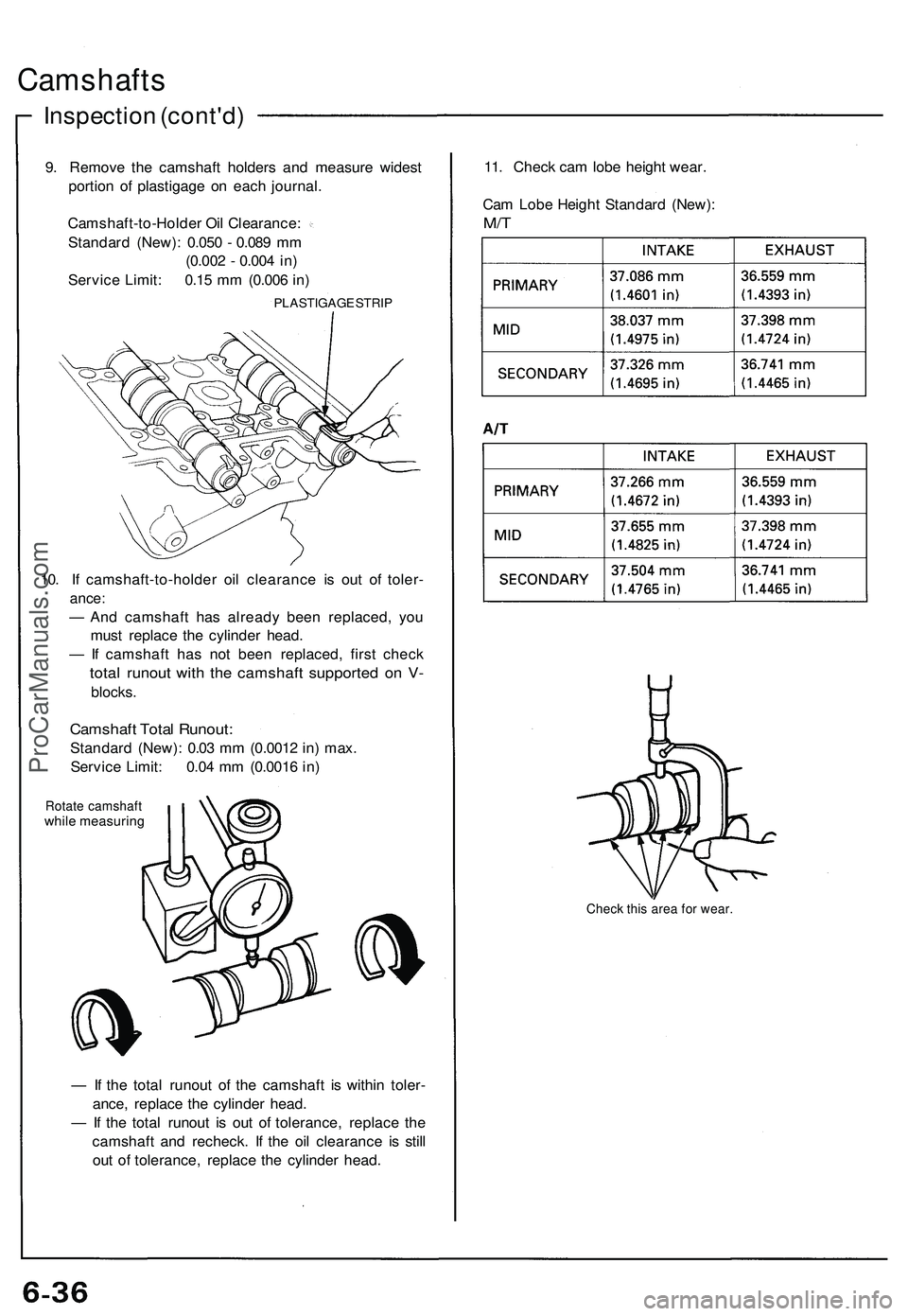
Camshafts
Inspection (cont'd)
9. Remove the camshaft holders and measure widest
portion of plastigage on each journal.
Camshaft-to-Holder Oil Clearance:
Standard (New): 0.050 - 0.089 mm
(0.002 - 0.004 in)
Service Limit: 0.15 mm (0.006 in)
PLASTIGAGE STRIP
10. If camshaft-to-holder oil clearance is out of toler-
ance:
— And camshaft has already been replaced, you
must replace the cylinder head.
— If camshaft has not been replaced, first check
total runout with the camshaft supported on V-
blocks.
Camshaft Total Runout:
Standard (New): 0.03 mm (0.0012 in) max.
Service Limit: 0.04 mm (0.0016 in)
Rotate camshaft
while measuring
— If the total runout of the camshaft is within toler-
ance, replace the cylinder head.
— If the total runout is out of tolerance, replace the
camshaft and recheck. If the oil clearance is still
out of tolerance, replace the cylinder head.
11. Check cam lobe height wear.
Cam Lobe Height Standard (New):
M/T
Check this area for wear.ProCarManuals.com
Page 456 of 1503
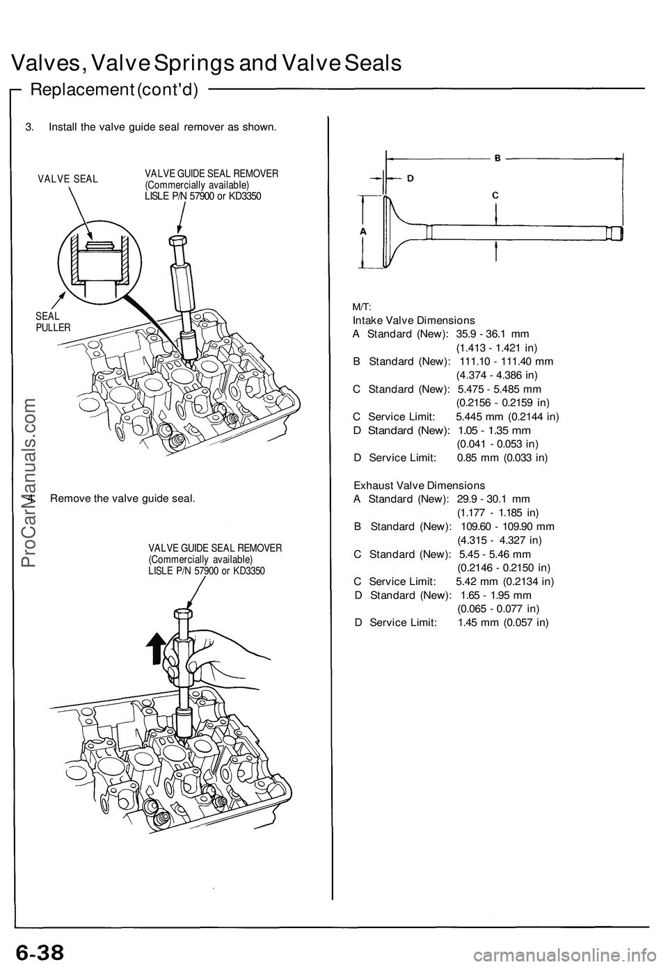
Valves, Valve Springs and Valve Seals
Replacement (cont'd)
3. Install the valve guide seal remover as shown.
VALVE SEAL
VALVE GUIDE SEAL REMOVER
(Commercially available)
LISLE P/N 57900 or KD3350
SEAL
PULLER
4. Remove the valve guide seal.
VALVE GUIDE SEAL REMOVER
(Commercially available)
LISLE P/N 57900 or KD3350
M/T:
Intake Valve Dimensions
A Standard (New): 35.9 - 36.1 mm
(1.413 - 1.421 in)
B Standard (New): 111.10 - 111.40 mm
(4.374 - 4.386 in)
C Standard (New): 5.475 - 5.485 mm
(0.2156 - 0.2159 in)
C Service Limit: 5.445 mm (0.2144 in)
D Standard (New): 1.05 - 1.35 mm
(0.041 - 0.053 in)
D Service Limit: 0.85 mm (0.033 in)
Exhaust Valve Dimensions
A Standard (New): 29.9 - 30.1 mm
(1.177 - 1.185 in)
B Standard (New): 109.60 - 109.90 mm
(4.315 - 4.327 in)
C Standard (New): 5.45 - 5.46 mm
(0.2146 - 0.2150 in)
C Service Limit: 5.42 mm (0.2134 in)
D Standard (New): 1.65 - 1.95 mm
(0.065 - 0.077 in)
D Service Limit: 1.45 mm (0.057 in)ProCarManuals.com