Page 457 of 1503
A/T:
Intake Valve Dimensions
A Standard (New): 34.9 - 35.1 mm
(1.374 - 1.382 in)
B Standard (New):
C Standard (New):
C Service Limit:
D Standard (New):
D Service Limit:
111.10-111.40 mm
(4.374 - 4.386 in)
5.475-5.485 mm
(0.2156-0.2159 in)
5.445 mm (0.2144 in)
1.05—1.35 mm
(0.041-0.053 in)
0.85 mm (0.033 in)
Exhaust Valve Dimensions
A
Standard (New):
29.9-30.1
mm
(1.177-1.185 in)
109.60-109.90
mm
(4.315-4.327 in)
5.45-5.46
mm
(0.2146-0.2150 in)
5.42 mm (0.2134 in)
1.65-1.95
mm
(0.065-0.077 in)
1.45 mm (0.057 in)
B Standard (New):
C Standard (New):
C Service Limit:
D Standard (New):
D Service Limit:ProCarManuals.com
Page 460 of 1503

Valve Guides
Valve Movement
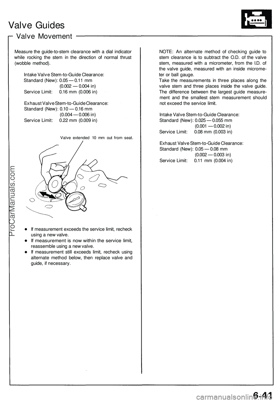
Measure the guide-to-stem clearance with a dial indicator
while rocking the stem in the direction of normal thrust
(wobble method).
Intake Valve Stem-to-Guide Clearance:
Standard (New): 0.05 — 0.11 mm
(0.002 — 0.004 in)
Service Limit: 0.16 mm (0.006 in)
Exhaust Valve Stem-to-Guide Clearance:
Standard (New): 0.10 — 0.16 mm
(0.004 — 0.006 in)
Service Limit: 0.22 mm (0.009 in)
Valve extended 10 mm out from seat.
If measurement exceeds the service limit, recheck
using a new valve.
If measurement is now within the service limit,
reassemble using a new valve.
If measurement still exceeds limit, recheck using
alternate method below, then replace valve and
guide, if necessary.
NOTE: An alternate method of checking guide to
stem clearance is to subtract the O.D. of the valve
stem, measured with a micrometer, from the I.D. of
the valve guide, measured with an inside microme-
ter or ball gauge.
Take the measurements in three places along the
valve stem and three places inside the valve guide.
The difference between the largest guide measure-
ment and the smallest stem measurement should
not exceed the service limit.
Intake Valve Stem-to-Guide Clearance:
Standard (New): 0.025 — 0.055 mm
(0.001 — 0.002 in)
Service Limit: 0.08 mm (0.003 in)
Exhaust Valve Stem-to-Guide Clearance:
Standard (New): 0.05 — 0.08 mm
(0.002 — 0.003 in)
Service Limit: 0.11 mm (0.004 in)ProCarManuals.com
Page 485 of 1503
Piston/Connecting Rod
Assemblies
Inspection
1. Check the piston for distortion or cracks.
NOTE: If cylinder is bored, an oversized piston
must be used.
2. Measure piston diameter at a point 17 mm (0.67 in)
from the bottom of the skirt.
NOTE: There are two standard-size pistons (A =
no letter and B). The letter is stamped on the top of
the piston. These letters are also stamped on the
block as cylinder bore sizes.
M/T:
Piston A (no letter) Diameter
Standard (New): 92.990 - 93.003 mm
(3.6610-3.6615 in)
Service Limit: 92.97 mm (3.6602 in)
Piston B Diameter
Standard (New): 92.980 - 92.993 mm
(3.6606-3.6611 in)
Service Limit: 92.96 mm (3.6598 in)
A/T:
Piston A (no letter) Diameter
Standard (New): 89.986 - 90.004 mm
(3.5427 - 3.5435 in)
Service Limit: 89.97 mm (3.5421 in)
Piston B Diameter
Standard (New): 89.976 - 89.994 mm
(3.5424 - 3.5431 in)
Service Limit: 89.96 mm (3.5417 in)ProCarManuals.com
Page 489 of 1503
Piston Rings
Ring-to-Groove Clearances
After installing a new set of rings, measure ring-to-groove
clearances:
Top Ring Clearance
M/T:
Standard (New): 0.035 - 0.065 mm
(0.0014-0.0026 in)
Service Limit: 0.13 mm (0.005 in)
A/T:
Standard (New): 0.030 - 0.055 mm
(0.0012 - 0.0022 in)
Service Limit: 0.13 mm (0.005 in)
Second Ring Clearance
M/T:
Standard (New): 0.030 - 0.060 mm
(0.0012-0.0024 in)
Service Limit: 0.13 mm (0.005 in)
A/T:
Standard (New): 0.030 - 0.055 mm
(0.0012-0.0022 in)
Service Limit: 0.13 mm (0.005 in)ProCarManuals.com
Page 565 of 1503

Engine Control Module (ECM) Reset Procedure
Either of the following actions, will reset the ECM.
Using the OBD II scan tool or Honda PGM Tester to clear the ECM's memory.
NOTE: See the OBD II scan tool or Honda PGM Tester user's manuals for specific operating instructions.
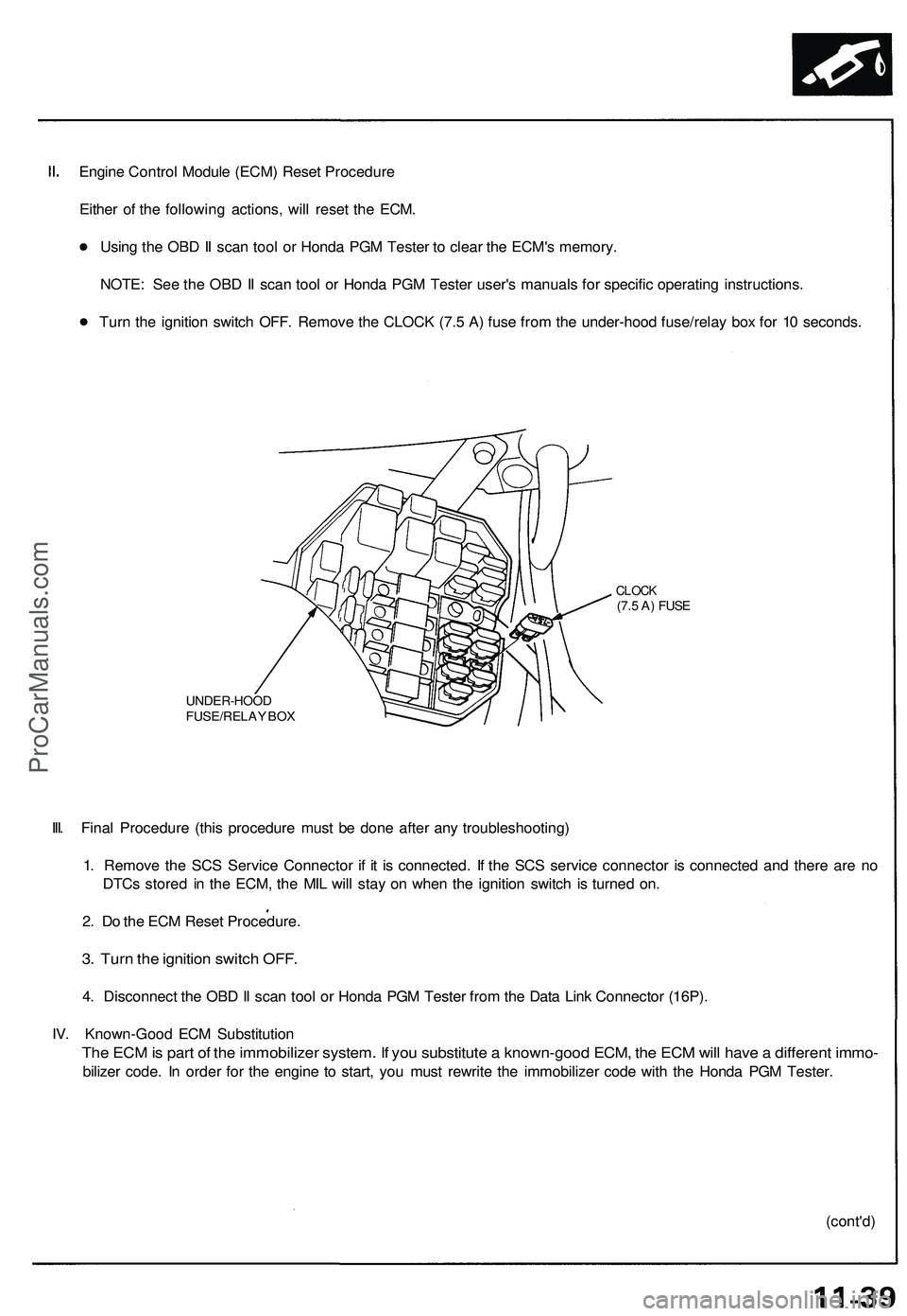
Turn the ignition switch OFF. Remove the CLOCK (7.5 A) fuse from the under-hood fuse/relay box for 10 seconds.
UNDER-HOOD
FUSE/RELAY BOX
CLOCK
(7.5 A) FUSE
III. Final Procedure (this procedure must be done after any troubleshooting)
1. Remove the SCS Service Connector if it is connected. If the SCS service connector is connected and there are no
DTCs stored in the ECM, the MIL will stay on when the ignition switch is turned on.
2. Do the ECM Reset Procedure.
3. Turn the ignition switch OFF.
4. Disconnect the OBD II scan tool or Honda PGM Tester from the Data Link Connector (16P).
IV. Known-Good ECM Substitution
The ECM is part of the immobilizer system. If you substitute a known-good ECM, the ECM will have a different immo-
bilizer code. In order for the engine to start, you must rewrite the immobilizer code with the Honda PGM Tester.
(cont'd)ProCarManuals.com
Page 586 of 1503

PGM-FI System
System Description (cont'd)
3. Fuel Cut-off Control
During deceleration with the throttle valve closed, current to the fuel injectors is cut off to improve fuel economy at
speeds over 1,500 rpm.
Fuel cut-off action also takes place when engine speed exceeds 8,300 rpm, regardless of the position of the throttle
valve, to protect the engine from over-revving.
4. A/C Compressor Clutch Relay
When the ECM receives a demand for cooling from the air conditioning system, it delays the compressor from being
energized, and enriches the mixture to assure smooth translation to the A/C mode.
5. Evaporative Emission (EVAP) Purge Control Solenoid Valve
When the engine coolant temperature is below 153°F (67°C), the ECM controls the EVAP purge control solenoid valve
which cuts vacuum to the EVAP purge control canister diaphragm.
6. Intake Air Bypass (IAB) Control Solenoid Valve
When the engine speed is below 4,800 rpm, the IAB control solenoid valve is activated by a signal from the ECM. Intake
air then flows through the smaller chamber, and high torque is delivered. To increase air flow at engine speeds higher
than 4,800 rpm, the solenoid valve is deactivated by the ECM, and the intake air flows through the larger chamber.
7. Exhaust Gas Recirculation (EGR) Control Solenoid Valve
When the EGR is required for control of oxides of nitrogen (NOx) emissions, the ECM supplies ground to the EGR
control solenoid valve which supplies regulated vacuum to the EGR valve.
ECM Fail-safe/Back-up Functions
1. Fail-Safe Function
When an abnormality occurs in a signal from a sensor, the ECM ignores that signal and assumes a pre-programmed
valve for that sensor that allows the engine to continue to run.
2. Back-up Function
When an abnormality occurs in the ECM itself, the fuel injectors are controlled by a back-up circuit independent of the
system in order to permit minimal driving.
3. Self-diagnosis Function [Malfunction Indicator Lamp (MIL)]
When an abnormality occurs in a signal from a sensor, the ECM lights the MIL and stores the diagnostic trouble code
in erasable memory. When the ignition is initially turned on, the ECM supplies ground for the MIL for two seconds to
check the MIL bulb condition.
4. Two Trip Detection Method
To prevent false indications, the Two Trip Detection Method is used for the H02S, fuel metering-related, idle control
system, ECT sensor, EGR system self-diagnostic functions and EVAP control system. When an abnormality occurs,
the ECM stores it in its memory. When the same abnormality recurs after the ignition switch is turned OFF and ON (II)
again, the ECM informs the driver by lighting the MIL.
However, to ease troubleshooting, this function is cancelled when you short the service check connector. The MIL will
then blink immediately when an abnormality occurs.
5. Two (or three) Driving Cycle Detection Method
A "Driving Cycle" consists of starting the engine, beginning closed loop operation, and stopping the engine. If misfir-
ing that increases emissions or EVAP control system malfunction is detected during two consecutive driving cycles,
or TWC deterioration is detected during three consecutive driving cycles, the ECM turns the MIL on.
However,
to
ease
troubleshooting,
this
function
is
cancelled when
you
short
the
service check connector.
The MIL
will
then blink immediately when an abnormality occurs.ProCarManuals.com
Page 646 of 1503
Clutch Disc
Inspection
1. Inspect the lining of the clutch disc for signs of slip-
page or oil. Replace it if it is burned black or oil
soaked.
2. Measure the clutch disc thickness.
3. Measure the depth from the lining surface to the
rivets, on both sides.
If the thickness is less than the service limit,
replace the clutch disc.
If the depth is less than the service limit, replace
the clutch disc.ProCarManuals.com
Page 667 of 1503
Reverse Shift Arm, Reverse Shift Fork
Clearance Inspection
1. Measure the clearance between the reverse shift
arm and the reverse shift piece.
2. If the clearance exceeds the service limit, measure
the width of the groove in the reverse shift arm.
If the width of the groove exceeds the standard,
replace the reverse shift arm with a new one.
If the width of the groove is within the standard,
replace the reverse shift piece with a new one.
If the width is less than the standard, replace the
reverse shift arm with a new one.
If the width is within the standard, replace the
reverse shift fork with a new one.
3. Measure the clearance between the reverse shift
arm and reverse shift fork.
4. If the
clearance exceeds
the
service
limit,
measure
the width of the reverse shift arm.ProCarManuals.com