Page 680 of 1202

(b) Using a be")
N00280
DENSO
Borroughs
CH0087
CORRECTWRONG WRONG
P13685
CH0732
Disconnect Wire
from Terminal B
Generator
Voltmeter BatteryAmmeter
B
- CHARGINGCHARGING SYSTEM
CH-3
1996 TERCEL (RM440U)
(b) Using a belt tension gauge, check the drive belt tension.
Belt tension gauge:
DENSO BTG-20 (95506-00020)
Borroughs No. BT-33-73F
Drive belt tension:
New belt
Used belt160 ± 20 lbf
100 ± 20 lbf
If the belt tension is not as specified, adjust it.
HINT:
�ºNew beltº refers to a belt which has been used less than
5 minutes on a running engine.
�ºUsed beltº refers to a belt which has been used on a run-
ning engine for 5 minutes or more.
�After installing a belt, check that it fits properly in the
ribbed grooved.
�Check by hand to confirm that the belt has not slipped out
of the groove on the bottom of the pulley.
�After installing a new belt, run the engine for about 5 min-
utes and recheck the belt tension.
4. VISUALLY CHECK GENERATOR WIRING AND
LISTEN FOR ABNORMAL NOISES
(a) Check that the wiring is in good condition.
(b) Check that there is no abnormal noise from the generator
while the engine is running.
5. INSPECT CHARGE WARNING LIGHT CIRCUIT
(a) Warm up the engine and then turn it off.
(b) Turn off all accessories.
(c) Turn the ignition switch ºONº. Check that the charge warn-
ing light is lit.
(d) Start the engine. Check that the light goes off.
If the light does not go off as specified, troubleshoot the charge
light circuit.
6. INSPECT CHARGING CIRCUIT WITHOUT LOAD
HINT:
If a battery/generator tester is available, connect the tester to
the charging circuit as per manufacturer's instructions.
(a) If a tester is not available, connect a voltmeter and amme-
ter to the charging circuit as follows:
�Disconnect the wire from terminal B of the generator
and connect it to the negative (-) tester probe of the
ammeter.
Page 776 of 1202
AX08K-01
D01644
Stop Light SwitchKey Interlock Solenoid
Shift Lock
Override Button
Shift Lock Control
Unit Assembly
BatteryMAIN
FLALTStopIgnition Switch
ACC
IGCIG
ECU-IG
Stop Light
Switch
Stop
LightSTPShift Lock
Control ECUIG ACC
Key Interlock Solenoid
KLS
+
E WIRING DIAGRAM
- AUTOMATIC TRANSAXLE (A132L)SHIFT LOCK SYSTEM
AX-23
775 Author�: Date�:
1996 TERCEL (RM440U)
SHIFT LOCK SYSTEM
LOCATION
Page 810 of 1202
AX084-01
D01645
Key Interlock Solenoid
Stop Light SwitchShift Lock
Override Button
Shift Lock Control
Unit Assembly
BatteryMAIN
FLALTStopIgnition Switch
ACC
IGCIG
ECU-IG
IG
Shift Lock
Control ECUACC
Key Interlock Solenoid
KLS
+
E Stop Light
Switch
Stop
LightSTP WIRING DIAGRAM
- AUTOMATIC TRANSAXLE (A242L)SHIFT LOCK SYSTEM
AX-27
809 Author�: Date�:
1996 TERCEL (RM440U)
SHIFT LOCK SYSTEM
LOCATION
Page 983 of 1202
RS0AZ-06
N12255
- SUPPLEMENTAL RESTRAINT SYSTEMFRONT PASSENGER AIRBAG ASSEMBLY
RS-21
1996 TERCEL (RM440U)
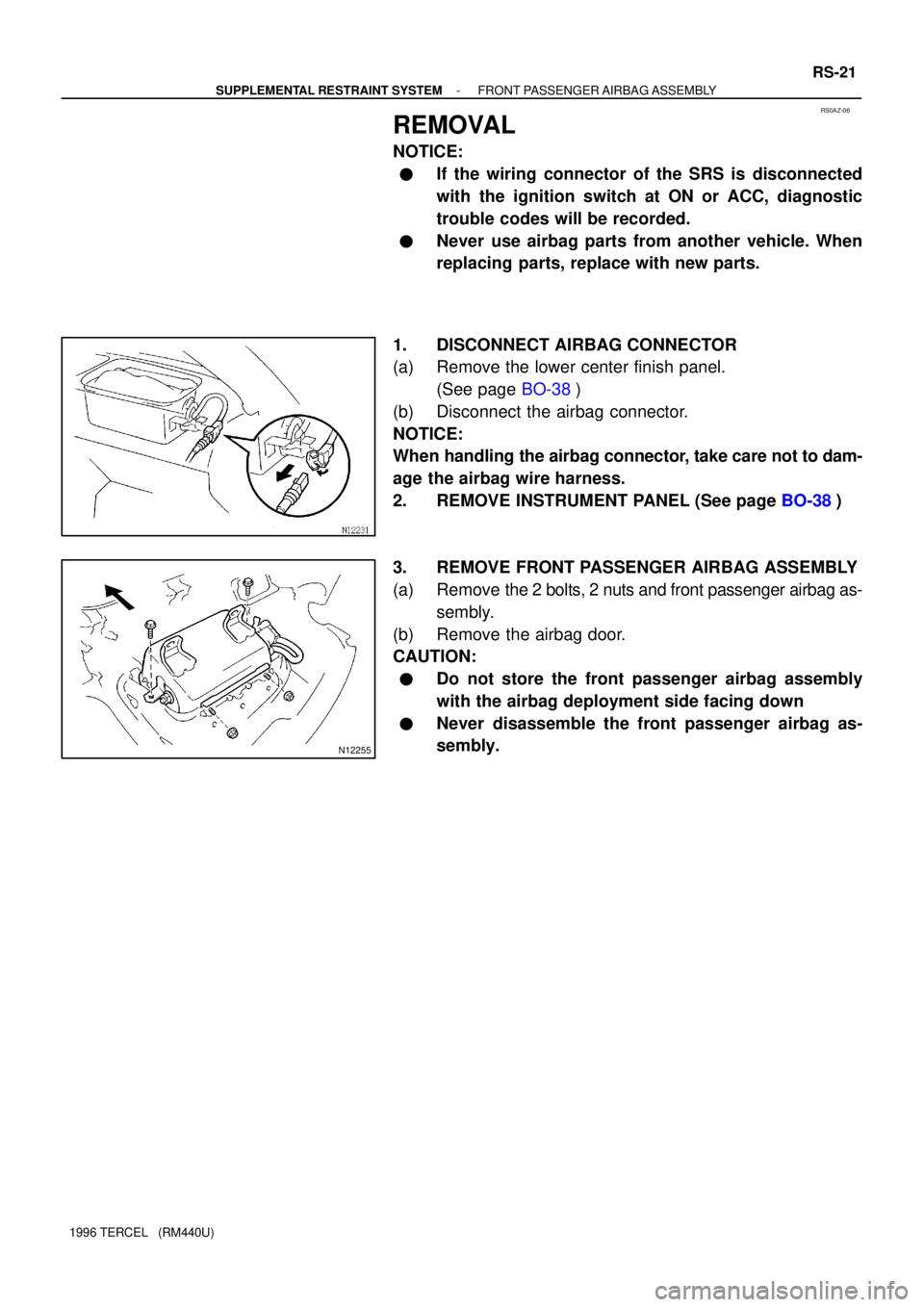
REMOVAL
NOTICE:
�If the wiring connector of the SRS is disconnected
with the ignition switch at ON or ACC, diagnostic
trouble codes will be recorded.
�Never use airbag parts from another vehicle. When
replacing parts, replace with new parts.
1. DISCONNECT AIRBAG CONNECTOR
(a) Remove the lower center finish panel.
(See page BO-38)
(b) Disconnect the airbag connector.
NOTICE:
When handling the airbag connector, take care not to dam-
age the airbag wire harness.
2. REMOVE INSTRUMENT PANEL (See page BO-38)
3. REMOVE FRONT PASSENGER AIRBAG ASSEMBLY
(a) Remove the 2 bolts, 2 nuts and front passenger airbag as-
sembly.
(b) Remove the airbag door.
CAUTION:
�Do not store the front passenger airbag assembly
with the airbag deployment side facing down
�Never disassemble the front passenger airbag as-
sembly.
Page 998 of 1202

INSTALLATION
NOTICE:
�Never use SRS parts from another vehicle. When re-
placing parts, replace with new par")
RS03C-13
RS-36
- SUPPLEMENTAL RESTRAINT SYSTEMAIRBAG SENSOR ASSEMBLY
1996 TERCEL (RM440U)
INSTALLATION
NOTICE:
�Never use SRS parts from another vehicle. When re-
placing parts, replace with new parts.
�Never reuse the airbag sensor assembly involved in
a collision when the airbag has deployed.
�Never repair a sensor in order to reuse it.
1. INSTALL AIRBAG SENSOR ASSEMBLY
(a) Using a torx wrench, install the airbag sensor assembly
with the 3 screws.
Torx wrench: T40 (Part No. 09042- 00020 or locally
manufactured tool)
Torque: 20 N´m (200 kgf´cm, 14 ft´lbf)
(b) Connect the connector.
NOTICE:
�Installation of the connector is done after the sensor
assembly has been installed.
�Make sure the sensor assembly is installed to the
specified torque.
�If the sensor assembly has been dropped, or there are
cracks, dents or other defects in the case, bracket or
connector, replace the sensor assembly with a new
one.
�When installing the airbag sensor assembly, take
care that the SRS wiring does not interfere with other
parts and is not pinched between other parts.
�After installation, shake the sensor assembly to
check that there is no looseness.
2. INSTALL THE REMOVED PARTS
Page 1037 of 1202

I16684
No.Wiring Connector Side
1
2
3
4
5
6
7GAUGE Fuse
10
11
12
13
1
2
3
4
5
7
8
1
2
3
4
5
6
7
8
9
10Generator
IGN Fuse
SRS Fuse
Airbag Sensor Assembly
Seat Belt Buckle Switch
Low Oil Pressure Warning Switch
Igniter
TAIL Fuse
Door Courtesy Switch
DOME Fuse
Fuel Level Warning Switch
Engine Coolant Temperature Sender Gauge
ABS ECU
ECM
O/D Off Switch
Light Control Rheostat
Ground
Headlight Dimmer Switch
Turn Signal Switch (Left) Ground
Fuel Sender Gauge
Theft Deterrent ECU
Speed Control Unit
Ground
Starter Relay
Brake Fluid Level Warning Switch
and Parking Brake Switch
Turn Signal Switch (Right) A
B
C
F
E
T: Fuel Receiver Gauge
: Engine Coolant Temperature Receiver Gauge
: Tachometer
Hi-Grade
SRS Warning Illumination Open Door Warning Hi-Beam Indicator Security Indicator Left Turn Indicator Right Turn Indicator Discharge Warning Seat Belt Warning O/D Off Indicator Brake WarningBulb Check Relay Malfunction Indicator Low Oil Pressure Warning ABS Warning Fuel Lever Warning Speed Sensor
A5 B7 A12 C2 A2
A6
B5 C9 B4 A7 B3 B1 A10 B8 B9 C7 C4
A4 A11 A13C1 C5C3 C10A3 C8C6 A1TE F BE-36
- BODY ELECTRICALCOMBINATION METER
1996 TERCEL (RM440U)
Page 1038 of 1202

I16685
No.Wiring Connector Side
1
2
3
4
5
6
7GAUGE Fuse
10
11
12
13
1
3
4
5
7
1
2
3
4
5
6
7
8
9
10Generator
IGN Fuse
SRS Fuse
Airbag Sensor Assembly
Seat Belt Buckle Switch
Low Oil Pressure Warning Switch
Igniter
TAIL Fuse
Door Courtesy Switch
DOME Fuse
Fuel Level Warning Switch
ABS ECU
ECM
O/D Off Switch
Light Control Rheostat
Headlight Dimmer Switch
Turn Signal Switch (Left) Ground
Fuel Sender Gauge
Theft Deterrent ECU
Speed Control Unit
Ground
Starter Relay
Brake Fluid Level Warning Switch
and Parking Brake Switch
Turn Signal Switch (Right) A
B
C
F
E
T: Fuel Receiver Gauge
: Engine Coolant Temperature Receiver Gauge
: Tachometer
8
9Ground
Engine Coolant Temperature Sender Gauge
A4 A11 A13C1 C5C3 C10A3 C8C6 A1
A5 B7 A12 C2 A2
A6
B5 C9 B4 A7 B3 B1 A10 A8 A9 C7 C4
SRS Warning Illumination Open Door Warning Hi-Beam Indicator Security Indicator Left Turn Indicator Right Turn Indicator Discharge Warning Seat Belt Warning O/D Off Indicator Brake WarningBulb Check Relay Malfunction Indicator Low Oil Pressure Warning ABS Warning
Fuel Lever Warning Speed Sensor TE F Lo-Grade
- BODY ELECTRICALCOMBINATION METER
BE-37
1996 TERCEL (RM440U)
Page 1084 of 1202
N15432
20 mm
(0.79 in.)
N12570
N00133
(4 Door)
(2 Door)
- BODYFRONT DOOR
BO-13
1996 TERCEL (RM440U)
CAUTION:
To avoid personal injury and shorting of the wiring when
installing (6.4 mm) rivets deep your hands and wire har-
ness out of the (20 mm) radius that caulked (6.4 mm) rivet
will cover.
14. REMOVE DOOR LOCK
(a) Remove the door lock control knob from the link.
(b) Disconnect the 2 links from the outside handle and the
door lock cylinder.
(c) Remove the 3 screws.
Torque: 5.4 N´m (55 kgf´cm, 48 in.´lbf)
HINT:
At the time of reassembly, refer to following pocedures.
�Apply adhesive to the 3 screws.
Part No.08833-00090, THREE BOND 1324 or equiva-
lent.
�Apply MP grease to the sliding and rotating parts of the
door lock.
15. REMOVE OUTSIDE HANDLE
16. REMOVE DOOR LOCK CYLINDER


N12570
N00133
(4 Door)
(2 Door)
- BODYFRONT DOOR
BO-13
1996 TERCEL (RM440U)
CAUTION:
To avoid personal injury and shorting of the wiring when
installing (6.4 mm) rivets deep")