Page 325 of 1202

H01461H04911
H05581
ABTerminal
Tc
ABOFF
Body
Ground
OFF
ON
OFF
Several
Seconds50 m sec.
50 m sec.
1 second
(± 0.5 sec.)
Tc
Body
Ground
1 second
(± 0.5 sec.)
1
23
45
N12278
DI-150
- DIAGNOSTICSSUPPLEMENTAL RESTRAINT SYSTEM
1996 TERCEL (RM440U)
4. DTC CLEARANCE (Using diagnosis check wire)
(a) Connect the 2 service wires to terminals Tc and AB of
DLC1.
(b) Turn the ignition switch to ACC or ON and wait approx. 6
seconds.
(c) Starting with the Tc terminal, apply body ground alternate-
ly to terminal Tc and terminal AB twice each in cycles of
1.0 seconds. Confirm that body ground is absolute. Final-
ly, keep applying body ground to terminal Tc.
HINT:
When alternately grounding terminals Tc and AB, release
ground from one terminal and immediately apply it to the other
terminal within an interval of 0.2 seconds. If DTCs do not clear,
repeat the above procedure until the codes are cleared.
(d) Several seconds after doing the clearing procedure, the
SRS warning light will blink in a 50 m sec. cycle to indicate
the codes have been cleared.
5. DTC CLEARANCE (Using TOYOTA hand-held tester)
(a) Hook up the TOYOTA hand-held tester to the DLC1.
(b) Clear the DTCs by following the prompts on the tester
screen.
HINT:
Please refer to the TOYOTA hand-held tester operator's manu-
al for further details.
Page 455 of 1202

P20382
Z00052
Z00054
44.5°
EM0181
Margin Thickness
- ENGINE MECHANICALCYLINDER HEAD
EM-33
1996 TERCEL (RM440U)
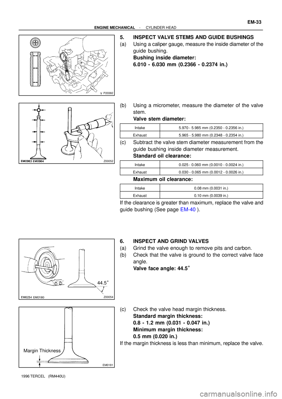
5. INSPECT VALVE STEMS AND GUIDE BUSHINGS
(a) Using a caliper gauge, measure the inside diameter of the
guide bushing.
Bushing inside diameter:
6.010 - 6.030 mm (0.2366 - 0.2374 in.)
(b) Using a micrometer, measure the diameter of the valve
stem.
Valve stem diameter:
Intake5.970 - 5.985 mm (0.2350 - 0.2356 in.)
Exhaust5.965 - 5.980 mm (0.2348 - 0.2354 in.)
(c) Subtract the valve stem diameter measurement from the
guide bushing inside diameter measurement.
Standard oil clearance:
Intake0.025 - 0.060 mm (0.0010 - 0.0024 in.)
Exhaust0.030 - 0.065 mm (0.0012 - 0.0026 in.)
Maximum oil clearance:
Intake0.08 mm (0.0031 in.)
Exhaust0.10 mm (0.0039 in.)
If the clearance is greater than maximum, replace the valve and
guide bushing (See page EM-40).
6. INSPECT AND GRIND VALVES
(a) Grind the valve enough to remove pits and carbon.
(b) Check that the valve is ground to the correct valve face
angle.
Valve face angle: 44.5°
(c) Check the valve head margin thickness.
Standard margin thickness:
0.8 - 1.2 mm (0.031 - 0.047 in.)
Minimum margin thickness:
0.5 mm (0.020 in.)
If the margin thickness is less than minimum, replace the valve.
Page 675 of 1202
ST1090
P25513
Terminal 30
Terminal 50
Ammeter
- STARTINGSTARTER (Planetary Type)
ST-29
1996 TERCEL (RM440U)
(b) Move the pinion gear toward the armature to remove
slack and measure the clearance between the pinion
gear end and stop collar.
Standard clearance: 1 - 5 mm (0.04 - 0.20 in.)
5. DO NO-LOAD PERFORMANCE TEST
(a) Connect the field coil lead to terminal C. Make sure the
lead is not grounded.
(b) Connect the battery and ammeter to the starter as shown.
(c) Check that the starter rotates smoothly and steadily with
the clutch pinion gear moving out. Check that the amme-
ter reads the specified current.
Specified current: At 11.5 V: 90 A or less