Page 289 of 1202
DI-1 14
- DIAGNOSTICSANTI-LOCK BRAKE SYSTEM
1996 TERCEL (RM440U)
(b) Check the DTC of speed sensor function.
Code No.DiagnosisTrouble Area
71Low output voltage of right front speed sensor�Right front speed sensor
�Sensor installation
72Low output voltage of left front speed sensor�Left front speed sensor
�Sensor installation
73Low output voltage of right rear speed sensor�Right rear speed sensor
�Sensor installation
74Low output voltage of left rear speed sensor�Left rear speed sensor
�Sensor installation
75Abnormal change in output voltage of right front speed sen-
sor�Right front speed sensor rotor
76Abnormal change in output voltage of left front speed sen-
sor�Left front speed sensor rotor
77Abnormal change in output voltage of right rear speed sen-
sor�Right rear speed sensor rotor
78Abnormal change in output voltage of left rear speed sensor�Left rear speed sensor rotor
Page 291 of 1202
DI4LR-01
W00983F15254
ABS ActuatorControl RelaySensor Rotor
Rear Speed Sensor ABS Warning Light
Sensor Rotor Front Speed Sensor
ABS ECU
DLC1
DI-1 16
- DIAGNOSTICSANTI-LOCK BRAKE SYSTEM
1996 TERCEL (RM440U)
PARTS LOCATION
Page 303 of 1202

BR3583
BR3582F00010
RotorSpeed Sensor
Magnet
To ECU
+V
-VHigh Speed
Low Speed
CoilNS
0 DI-128
- DIAGNOSTICSANTI-LOCK BRAKE SYSTEM
1996 TERCEL (RM440U)
DTC 31, 32, 33, 34 Speed Sensor Circuit
CIRCUIT DESCRIPTION
The speed sensor detects wheel speed and sends the ap-
propriate signals to the ECU. These signals are used to control
the ABS system. The front and rear rotors each have 48 serra-
tions.
When the rotors rotate, the magnetic field emitted by the perma-
nent magnet in the speed sensor generates an AC voltage.
Since the frequency of this AC voltage changes in direct propor-
tion to the speed of the rotors, the frequency is used by the ECU
to detect the speed of each wheel.
DTC No.DTC Detecting ConditionTrouble Area
31, 32, 33, 34
Detection of any of conditions 1 through 3:
1. At vehicle speed of 10 km/h (6 mph) or more, pulses are
not input for 5 sec.
2. Momentary interruption of the speed sensor signal oc-
curs at least 7 times in the time between switching the
ignition switch ON and switching it OFF
3. Abnormal fluctuation of speed sensor signals with the
vehicle speed 20 km/h (12 mph) or more
�Right front, left front, right rear or left rear speed sensor
�Open or short in each speed sensor circuit
�ECU
HINT:
�DTC 31 is for the right front speed sensor.
�DTC 32 is for the left front speed sensor.
�DTC 33 is for the right rear speed sensor.
�DTC 34 is for the left rear speed sensor.
Fail safe function:
If trouble occurs in the speed sensor circuit, the ECU cuts off current to the ABS control (solenoid) relay and
prohibits ABS control.
DI983-01
Page 306 of 1202

R00948
BR4248
BR3795
OK NG
- DIAGNOSTICSANTI-LOCK BRAKE SYSTEM
DI-131
1996 TERCEL (RM440U)
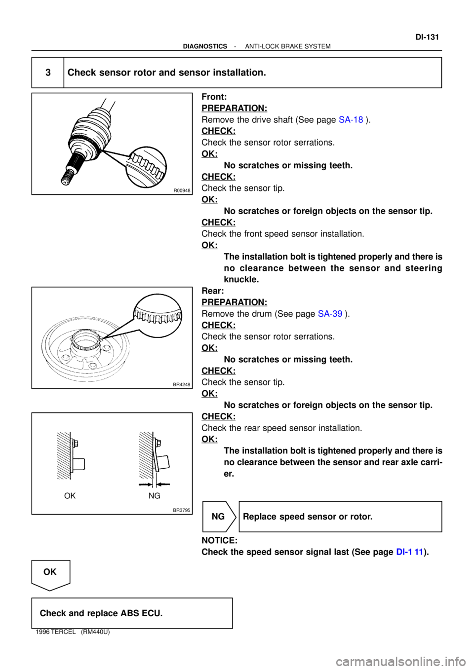
3 Check sensor rotor and sensor installation.
Front:
PREPARATION:
Remove the drive shaft (See page SA-18).
CHECK:
Check the sensor rotor serrations.
OK:
No scratches or missing teeth.
CHECK:
Check the sensor tip.
OK:
No scratches or foreign objects on the sensor tip.
CHECK:
Check the front speed sensor installation.
OK:
The installation bolt is tightened properly and there is
no clearance between the sensor and steering
knuckle.
Rear:
PREPARATION:
Remove the drum (See page SA-39).
CHECK:
Check the sensor rotor serrations.
OK:
No scratches or missing teeth.
CHECK:
Check the sensor tip.
OK:
No scratches or foreign objects on the sensor tip.
CHECK:
Check the rear speed sensor installation.
OK:
The installation bolt is tightened properly and there is
no clearance between the sensor and rear axle carri-
er.
NG Replace speed sensor or rotor.
NOTICE:
Check the speed sensor signal last (See page DI-1 11).
OK
Check and replace ABS ECU.
Page 835 of 1202

SA128-02
FA1535
SST
F03986
SA-18
- SUSPENSION AND AXLEFRONT DRIVE SHAFT
1996 TERCEL (RM440U)
REMOVAL
NOTICE:
�The hub bearing could be damaged if it is subjected
to the vehicle weight, such as when moving the ve-
hicle with the drive shaft removed. Therefore, if it is
absolutely necessary to place the vehicle weight on
the hub bearing, first support it with SST.
SST 09608-16042 (09608-02021, 09608-02041)
�w/ ABS:
After disconnecting the drive shaft from the axle hub,
work carefully so as not to damage the sensor rotor
serrations on the drive shaft.
1. REMOVE FRONT WHEEL
Torque: 103 N´m (1,050 kgf´cm, 76 ft´lbf)
2. M/T:
REMOVE LH ENGINE UNDER COVER
3. DRAIN TRANSAXLE OIL (M/T) OR ATF (A/T)
4. w/ ABS:
REMOVE BOLT AND ABS SPEED SENSOR
Torque: 7.8 N´m (80 kgf´cm, 69 in.´lbf)
5. REMOVE DRIVE SHAFT LOCK NUT
(a) Remove the cotter pin and lock cap.
(b) While applying the brakes, remove the nut.
Torque: 216 N´m (2,200 kgf´cm, 159 ft´lbf)
6. DISCONNECT TIE ROD END FROM STEERING
KNUCKLE (See page SA-10)
7. DISCONNECT LOWER BALL JOINT FROM LOWER
SUSPENSION ARM (See page SA-10)
8. DISCONNECT DRIVE SHAFT FROM AXLE HUB
NOTICE:
Be careful not to damage the drive shaft boot and inner oil
seal.
Page 894 of 1202
BR0S4-05
R15521
Fender Liner
Front Speed
Sensor
Sensor Rotor
- BRAKEFRONT SPEED SENSOR
BR-41
915 Author�: Date�:
1996 TERCEL (RM440U)
FRONT SPEED SENSOR
COMPONENTS
Page 897 of 1202
BR0S7-06
R15522
Sensor Rotor
Brake Drum
Outer Bearing
Nut Lock
Grease Cap Claw Washer
� Cotter Pin Rear Speed Sensor
� Non-reusable part BR-44
- BRAKEREAR SPEED SENSOR
918 Author�: Date�:
1996 TERCEL (RM440U)
REAR SPEED SENSOR
COMPONENTS