Page 982 of 1354
LU0O4−01
S01775S01237B13839
M/T
A/T
S01375
P04282
SST
SST
− LUBRICATIONOIL PUMP
LU−7
1996 RAV4 (RM447U)
REMOVAL
HINT:
When repairing the oil pump, the oil pan and strainer should be
removed and cleaned.
1. REMOVE HOOD
2. REMOVE RH ENGINE UNDER COVER
3. DRAIN ENGINE OIL
4. REMOVE FRONT EXHAUST PIPE (See page EM−33)
5. REMOVE STIFFENER PLATE
Remove the 2 bolts (M/T) or 3 bolts (A/T) and stiffener plate.
6. REMOVE OIL PAN
(a) Remove the dipstick.
(b) Remove the 17 bolts and the 2 nuts.
(c) Insert the blade of SST between the cylinder block and oil
pan, and cut off applied sealer and remove the oil pan.
SST 09032−00100
NOTICE:
�Do not use SST for the oil pump body side and rear oil
seal retainer.
�Be careful not to damage the oil pan flange.
Page 983 of 1354
P04349
S02326
Engine
Hanger
No.1
S01635
SST
S01599
S01581
LU−8
− LUBRICATIONOIL PUMP
1996 RAV4 (RM447U)
7. REMOVE OIL PAN BAFFLE PLATE AND OIL STRAIN-
ER
Remove the 2 bolts, 2 nuts, oil strainer, baffle plate and gasket.
8. SUSPEND ENGINE WITH ENGINE SLING DEVICE
Install a engine hanger No. 1 in the correct direction.
Part No. :
Engine hanger No. 1 12281−74060
Bolt 91611−B1020
Torque: 25 N·m (250 kgf·cm, 18 ft·lbf)
9. REMOVE TIMING BELT (See page EM−15)
10. REMOVE NO.2 IDLER PULLEY AND CRANKSHAFT
TIMING PULLEY (See page EM−81)
11. REMOVE OIL PUMP PULLEY
Using SST, remove the nut and pulley.
SST 09960−10010 (09962−01000, 09963−00600)
12. REMOVE CRANKSHAFT POSITION SENSOR
(a) Disconnect the connector from the generator drive belt
adjusting bar.
(b) Remove the bolt and crankshaft position sensor.
13. REMOVE OIL PUMP
(a) Remove the 12 bolts.
Page 986 of 1354
LU065−02
P04232
P04350
P04233
− LUBRICATIONOIL PUMP
LU−11
1996 RAV4 (RM447U)
INSPECTION
1. INSPECT RELIEF VALVE
Coat the valve with engine oil and check that it falls smoothly
into the valve hole by its own weight.
If it doesn’t, replace the relief valve. If necessary, replace the oil
pump assembly.
2. INSPECT DRIVE AND DRIVEN ROTORS
3. INSPECT ROTOR BODY CLEARANCE
Using a feeler gauge, measure the clearance between the driv-
en rotor and body.
Standard body clearance:
0.10 − 0.16 mm (0.0039 − 0.0063 in.)
Maximum body clearance:
0.20 mm (0.0079 in.)
If the body clearance is greater than maximum, replace the ro-
tors as a set. If necessary, replace the oil pump assembly.
4. INSPECT ROTOR TIP CLEARANCE
Using a feeler gauge, measure the clearance between the drive
and driven rotor tips.
Standard tip clearance:
0.04 − 0.16 mm (0.0016 − 0.0063 in.)
Maximum tip clearance:
0.20 mm (0.0079 in.)
If the tip clearance is greater than maximum, replace the rotors
as a set.
Page 989 of 1354

LU0O5−01
Z17341
A
B AA A
A A
A
AAA
B
S01599
S01633
SST LU−14
− LUBRICATIONOIL PUMP
1996 RAV4 (RM447U)
INSTALLATION
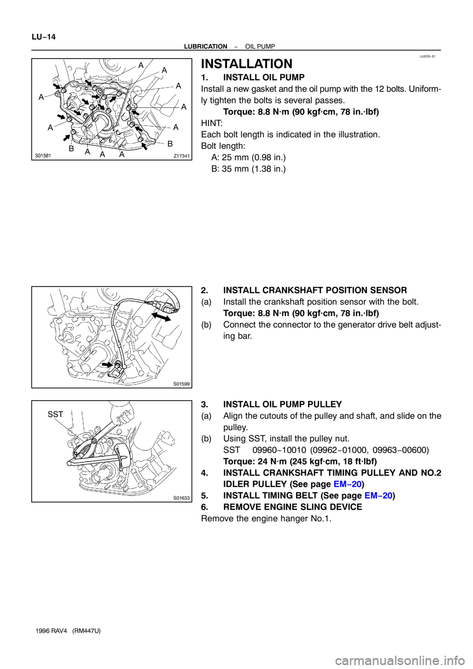
1. INSTALL OIL PUMP
Install a new gasket and the oil pump with the 12 bolts. Uniform-
ly tighten the bolts is several passes.
Torque: 8.8 N·m (90 kgf·cm, 78 in.·lbf)
HINT:
Each bolt length is indicated in the illustration.
Bolt length:
A: 25 mm (0.98 in.)
B: 35 mm (1.38 in.)
2. INSTALL CRANKSHAFT POSITION SENSOR
(a) Install the crankshaft position sensor with the bolt.
Torque: 8.8 N·m (90 kgf·cm, 78 in.·lbf)
(b) Connect the connector to the generator drive belt adjust-
ing bar.
3. INSTALL OIL PUMP PULLEY
(a) Align the cutouts of the pulley and shaft, and slide on the
pulley.
(b) Using SST, install the pulley nut.
SST 09960−10010 (09962−01000, 09963−00600)
Torque: 24 N·m (245 kgf·cm, 18 ft·lbf)
4. INSTALL CRANKSHAFT TIMING PULLEY AND NO.2
IDLER PULLEY (See page EM−20)
5. INSTALL TIMING BELT (See page EM−20)
6. REMOVE ENGINE SLING DEVICE
Remove the engine hanger No.1.
Page 991 of 1354
S01775S01237B13839
A/T M/T LU−16
− LUBRICATIONOIL PUMP
1996 RAV4 (RM447U)
9. INSTALL STIFFENER PLATE
Install the stiffener plate with the 2 bolts (M/T) or 3 bolts (A/T).
Torque: 37 N·m (380 kgf·cm, 27 ft·lbf)
10. INSTALL FRONT EXHAUST PIPE (See page EM−55)
11. FILL WITH ENGINE OIL
12. START ENGINE AND CHECK FOR LEAKS
13. RECHECK ENGINE OIL LEVEL
14. INSTALL RH ENGINE UNDER COVER
15. INSTALL HOOD
Page 993 of 1354
LU06A−03
S01365
S01359
SST
S01366
LU−18
− LUBRICATIONOIL COOLER
1996 RAV4 (RM447U)
REMOVAL
1. REMOVE RH ENGINE UNDER COVER
2. DRAIN ENGINE COOLANT
3. REMOVE FRONT EXHAUST PIPE (See page EM−33)
4. REMOVE GENERATOR (See page CH−7)
5. REMOVE OIL DIPSTICK
6. REMOVE EXHAUST MANIFOLD AND FRONT TWC
ASSEMBLY (See page EM−33)
7. REMOVE WATER BYPASS PIPE HEAT PROTECTOR
Remove the bolt, 2 nuts and heat protector.
8. REMOVE OIL FILTER
Using SST, remove the oil filter.
SST 09228−06501
9. REMOVE OIL COOLER
(a) Disconnect the 2 water bypass hoses from the oil cooler.
(b) Remove the union bolt and plate washer.
(c) Remove the nut and oil cooler.
(d) Remove the O−ring from the oil cooler.
Page 995 of 1354
LU06C−02
LU−20
− LUBRICATIONOIL COOLER
1996 RAV4 (RM447U)
INSTALLATION
1. INSTALL OIL COOLER
(a) Clean the oil cooler contact surface on the oil cooler
mounting.
(b) Install a new O−ring to the oil cooler.
(c) Temporarily install the oil cooler with the nut.
(d) Apply a light coat of engine oil on the threads and under
the head of the relief valve.
(e) Install the plate washer and union bolt.
Torque: 78 N·m (800 kgf·cm, 58 ft·lbf)
(f) Tighten the nut.
Torque: 8.8 N·m (90 kgf·cm, 78 in.·lbf)
(g) Connect the 2 water bypass hoses to the oil cooler.
2. INSTALL OIL FILTER
3. INSTALL WATER BYPASS HOSE HEAT PROTECTOR
Install the heat protector with the bolt and 2 nuts.
4. INSTALL EXHAUST MANIFOLD AND FRONT TWC AS-
SEMBLY (See page EM−55)
5. INSTALL OIL DIPSTICK
6. INSTALL GENERATOR (See page CH−19)
7. INSTALL FRONT EXHAUST PIPE (See page EM−55)
8. FILL WITH ENGINE COOLANT
9. START ENGINE AND CHECK FOR LEAKS
10. CHECK ENGINE OIL LEVEL
11. INSTALL RH ENGINE UNDER COVER
Page 997 of 1354

MX05N−02
Q10400
Air Intake Connector
Engine Coolant
Reservoir Tank Clutch Release Cylinder
and Line
Vehicle Speed
Sensor Connector
Back−Up Light Switch
Connector
Control Cable
Clip
Ground Cable
Transaxle Case Protector
Tie Rod End RH Drive Shaft
Stiffener PlateNo.2 Rear
End Plate
� Snap Ring
� Cotter Pin LH Drive
Shaft
PS Gear Assembly
Engine Mounting
Center Member
RH Engine
Under Cover
LH Engine Under CoverFront Suspension Crossmember
Assembly with Stabilizer BarClipAir Cleaner Case
Assembly
with Air Hose
Snap Ring
Engine
Wire
Clamp
� Cotter Pin
Lock Cap Starter
N·m (kgf·cm, ft·lbf): Specified torque
� Non−reusable part�
� �
4.9 (50, 43 in.·lbf)
12 (120, 9)
29 (300, 22)
35 (360, 26)32 (330, 24)46 (470, 34)
64 (650, 47)
35 (360, 26)
64 (650, 47)
12 (120, 9)
64 (650, 47)
25 (250, 18)
25 (250, 18)
9.0 (95, 78 in.·lbf)
37 (380, 27)
39 (400, 29)
9.0 (95, 78 in.·lbf)
29 (300, 22)
37 (380, 27)49 (500, 36)
113 (1,150, 83)
137 (1,400, 101)
206 (2,100, 152)
216 (2,200, 159)
113 (1,150, 83)
64 (650, 47)
48 (490, 35)
80 (820, 59)
115 (1,170, 85)
127 (1,300, 94)
�62 (630, 46)
Front Exhaust Pipe
� GasketClip
Washer
MX−2
− MANUAL TRANSAXLEMANUAL TRANSAXLE UNIT (2WD)
1996 RAV4 (RM447U)
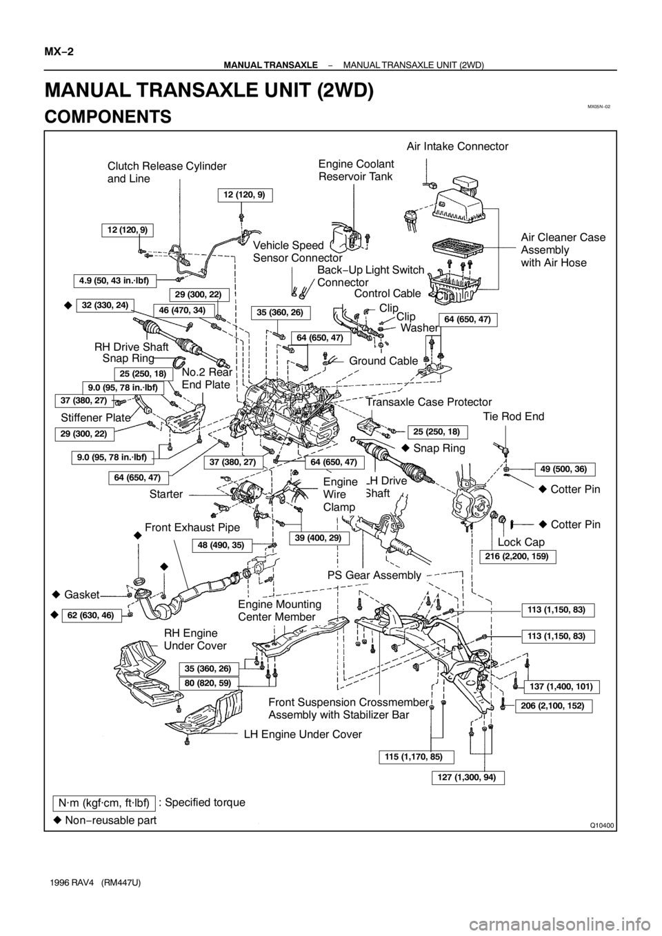
MANUAL TRANSAXLE UNIT (2WD)
COMPONENTS